Coupling process of waste heat recovery and denitrification of sintering dust

A soot and denitrification technology, which is applied in the flue gas denitrification process and sintering flue gas circulation low NOx emission process, can solve the problems of reducing the cost of SCR denitrification, large investment in denitrification treatment, and long process route, so as to save power consumption, Reduce the cost of denitrification and reduce the effect of investment

Active Publication Date: 2020-06-02
武汉钢铁有限公司 +2
View PDF11 Cites 0 Cited by
  • Summary
  • Abstract
  • Description
  • Claims
  • Application Information

AI Technical Summary

Problems solved by technology

[0006] The purpose of the present invention is to solve the above technical problems, aiming at the common problems of long sintering flue gas treatment process route, large denitrification treatment investment and high cost, combined with the sintering flue dust rich in iron oxides, with NH 3 - The characteristics of SCR denitrification catalytic performance, providing a simple process flow, flue gas separation and treatment without purchasing denitrification catalysts to achieve self-catalytic denitrification of soot, compact structure, high waste heat recovery rate, low investment in denitrification equipment, low denitrification operation costs, and denitrification Catalyst and flue gas heating energy consumption zero input sintering fume separation waste heat recovery and denitrification coupling process can effectively use the waste heat of sintering flue gas for online denitrification, greatly reducing the cost of existing SCR denitrification

Method used


Image

  • Coupling process of waste heat recovery and denitrification of sintering dust
  • Coupling process of waste heat recovery and denitrification of sintering dust
  • Coupling process of waste heat recovery and denitrification of sintering dust

Examples


Embodiment Construction

[0033] The system of the present invention will be further explained below in conjunction with the accompanying drawings:

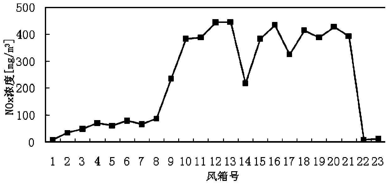
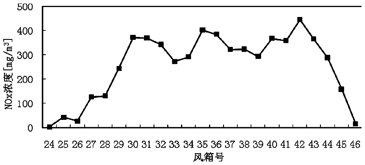
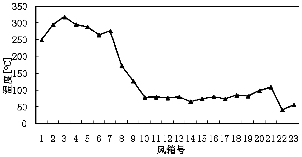
[0034] see image 3 , the system of the present invention includes a sintering machine 2, a bellows 6 is provided under the trolley 2.1 of the sintering machine 2, and the outlet at the bottom of the bellows 6 is connected to the flue pipe, and the sintering machine 2 is divided into an ignition section, a machine There are four areas: the head section, the flue gas rapid heating section and the tail section. The flue gas pipeline includes the high-temperature flue gas main flue 10 , the circulating flue gas main flue 16 and the nose ignition section flue 13 .

[0035] The outlet of the air box 6 below the tail section and the flue gas rapid heating section is respectively connected to the high-temperature flue gas main flue 10 through the corresponding fluidized bed reactor 8, and the high-temperature flue gas main flue 10 passes through the flue gas hea...


PUM


Abstract

The invention relates to a sintering smoke quality-divided treatment, waster heat recycling and denitration coupling process. The process is characterized in that sintering smoke passes through a sinter bed, bed charge, a grate at the bottom of a sintering machine trolley and an air box under the sintering machine trolley and then enters a flue gas pipeline; the sintering smoke at a machine tail section and a rapid flue gas heating section passes through air boxes and fluidized bed reactors which correspond to the machine tail section and the rapid flue gas heating section, and then enters a main flue of high-temperature flue gas; the sintering smoke coming from a machine head section is collected by a corresponding air box, is then led out through a main flue of circulatory flue gas, is sent into a circulatory flue gas hood arranged above the sintering machine trolley, and enters the sinter bed again under the action of suction force of a high pressure draft fan; the sintering smoke coming from an ignition section is collected by a corresponding air box and then enters a flue of a machine head ignition section. The process provided by the invention is simple in process flow; a denitration catalyst does not need to be additionally purchased during flue gas quality-divided treatment, so that self-catalysis denitration of the smoke is realized; the process is compact in structure, high in recovery rate of waste heat, less in denitration equipment investment, low in denitration running cost, zero in input of the denitration catalyst and free from flue gas heating energy consumption.

Description

technical field [0001] The invention relates to a flue gas denitrification process in the field of environmental protection, in particular to a sintering flue gas circulation low NOx emission process. Background technique [0002] During the "Twelfth Five-Year Plan" period, my country's key statistical steel industry SO 2 The emission is 2.51 million tons / year, of which SO 2 The emissions reached 2.18 million tons, accounting for more than 87% of the total emissions of iron and steel enterprises. By the end of the "Twelfth Five-Year Plan", sintering SO 2 The treatment rate is only 88%. In terms of denitrification, it has not yet been fully developed. [0003] The characteristics of sintering flue gas are large flue gas volume, large amount of dust carried by flue gas, large changes in emission and concentration of sulfur dioxide, large fluctuations in flue gas temperature, complex flue gas components, and high moisture content in flue gas. Compared with boiler flue gas, ...

Claims


Application Information

Patent Timeline
Patent Type & Authority Patents(China)
IPC IPC(8): B01D53/90B01D53/56
CPCB01D53/343B01D53/8631B01D53/90B01D2251/2062B01D2255/20738B01D2258/0283
Inventor 吴高明吴晓晖付本全
Owner 武汉钢铁有限公司
Why Eureka
Try Eureka