Brake system

A braking system and braking force technology, applied in electric braking systems, braking control systems, brakes, etc., to achieve excellent responsiveness and good energy efficiency

Active Publication Date: 2017-08-22
TOYOTA JIDOSHA KK
View PDF8 Cites 9 Cited by
  • Summary
  • Abstract
  • Description
  • Claims
  • Application Information

AI Technical Summary

Problems solved by technology

That is, the braking force applied by the hydraulic braking device has to be controlled based on the braking force applied by the regenerative braking devic...

Method used


Image

  • Brake system
  • Brake system
  • Brake system

Examples


no. 1 example

[0078] [A] Outline of vehicle drive system and braking system

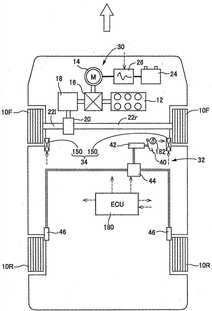
[0079] Vehicles equipped with the braking system of the first embodiment are as follows: figure 1 As shown schematically, it is a hybrid vehicle in which the front wheels 10F and the rear wheels 10R each have two wheels, and the two front wheels 10F are driving wheels. First, a vehicle drive system will be described. The vehicle drive system mounted on the vehicle includes an engine 12 and an electric motor 14 as two drive sources, and the engine 12 and electric motor 14 are connected via a power distribution mechanism 16 . The left and right front wheels 10F are driven via the final reduction gear 18 , the differential mechanism 20 , and the drive shafts 22 l and 22 r based on the output from the power distribution mechanism 16 . The operation of the electric motor 14 is performed by controlling the inverter 26 interposed between the electric motor 14 and the battery 24 .

[0080] The braking system of the embo...

no. 2 example

[0131] [A] Structure of the vehicle drive system and braking system of the second embodiment

[0132] Vehicles equipped with the braking system of the second embodiment such as Figure 7 Schematically, the two rear wheels 10R are drive wheels. Most of the vehicle drive system and brake system are structurally the same as those of the vehicle equipped with the brake system of the first embodiment. Therefore, the same reference numerals are assigned to the same functional elements and descriptions thereof are omitted. In the vehicle drive system, since both rear wheels 10R are drive wheels, the final reduction gear 18 and the differential mechanism 20 are connected by a propeller shaft 190 extending in the vehicle front-rear direction.

[0133] The braking system of the second embodiment is as Figure 7Schematically shown, the regenerative braking device 30 and the electric braking device 34 respectively impart regenerative braking force and electric braking force to each of t...

no. 3 example

[0139] [A] Structure of the vehicle drive system and braking system of the third embodiment

[0140] Vehicles equipped with the brake system of the third embodiment such as Figure 8 Schematically, the two front wheels 10F are drive wheels. The vehicle drive system and the braking system are largely the same in structure as the vehicle equipped with the braking system of the first embodiment, and therefore, the same reference numerals are used for the components having the same functions, and description thereof will be omitted.

[0141] The brake system of the third embodiment is as Figure 8 Schematically shown, the regenerative braking device 30 and the hydraulic braking device 32 respectively impart regenerative braking force and hydraulic braking force to each of the two front wheels 10F as drive wheels, and the electric braking device 34 applies the electric braking force Assigned to each of the two rear wheels 10R.

[0142] [B] Control of braking force

[0143] The ...


PUM


Abstract

The invention provides a brake system. The project of the system is to improve the practicability of the brake system comprising a regenerative brake device. The brake system is constructed as: a braking force generated by a hydraulic brake device is given to one of front wheel (10R) and rear wheel (10R), a braking force generated by an electric brake device is given to another one, a braking force generated by the regenerative brake device is given to any one of the wheels, and a braking force obtained by excluding the braking force generated by the hydraulic brake device from a required overall braking force required for the vehicle as a whole is controlled through controlling the electric brake device and the regenerative brake device, wherein the brake system is configured such that the hydraulic brake device gives the braking force when the required overall braking force exceeds a threshold. The brake system has good responsiveness, and the vehicle having the brake system has good energy efficiency.

Description

technical field [0001] The present invention relates to a braking system mounted on a vehicle, specifically, a braking system including a regenerative braking device. Background technique [0002] A vehicle brake system is generally composed mainly of a hydraulic brake device that applies braking force depending on the pressure of working fluid. As an example of this hydraulic brake device, as shown in the following patent documents, there is a configuration that applies braking force by control. Hydraulic brake device with arbitrary braking force. On the other hand, recently, hybrid vehicles have attracted attention. In hybrid vehicles, braking force can generally be obtained by using a regenerative braking device. It can also be used in the braking system of the vehicle. [0003] Patent Document 1: Japanese Patent Laid-Open No. 2004-338582 [0004] In the braking system including the hydraulic braking device and the regenerative braking device described in the above-men...

Claims


Application Information

Patent Timeline
IPC IPC(8): B60T13/58B60T13/68B60T13/74B60T8/36
CPCB60T8/36B60T13/588B60T13/686B60T13/74B60T2270/60B60L7/26B60L15/2009B60T7/042B60T8/267B60T13/146B60T13/586B60T13/741B60T2270/604B60L50/16Y02T10/64Y02T10/7072Y02T10/72B60T8/171B60T8/172B60T8/26B60T2270/608Y02T10/70
Inventor 山本直树
Owner TOYOTA JIDOSHA KK
Why Eureka
Try Eureka