Shield spiral conveyor and shield tunneling machine

A technology of screw conveyor and shield screw, which is used in mining equipment, earth-moving drilling, tunnels, etc., can solve the problems of unfavorable screw conveyor arrangement and lifting, poor stability and adjustment performance, and long screw conveyor length. , to achieve the effect of small occupied space, avoiding pollution and high service life

Inactive Publication Date: 2017-08-22
CHINA RAILWAY CONSTR HEAVY IND
View PDF6 Cites 1 Cited by
  • Summary
  • Abstract
  • Description
  • Claims
  • Application Information

AI Technical Summary

Problems solved by technology

The driving and sealing method of the existing shield screw conveyor mainly adopts the combination of copper sleeve and rubber seal, and the transmission stability and adjustment performance of the copper sleeve seal are poor. The space occupation is large, which leads to the length of the screw conveyor is too long, which is not conducive to the layout and lifting of the screw conveyor; and the rubber seal is used, the rubber is easily broken down by the high pressure of the soil, and it is easy to be driven by the rotating cylinder to rotate together. Good sealing performance cannot be guaranteed

Method used


Image

  • Shield spiral conveyor and shield tunneling machine
  • Shield spiral conveyor and shield tunneling machine

Examples


Embodiment Construction

[0024] The present invention will be described in further detail below in conjunction with the accompanying drawings and specific embodiments, but the protection scope of the present invention is not limited thereby.

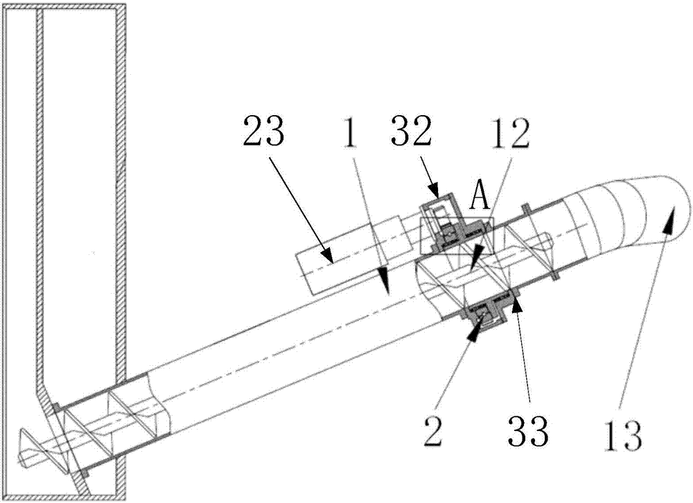
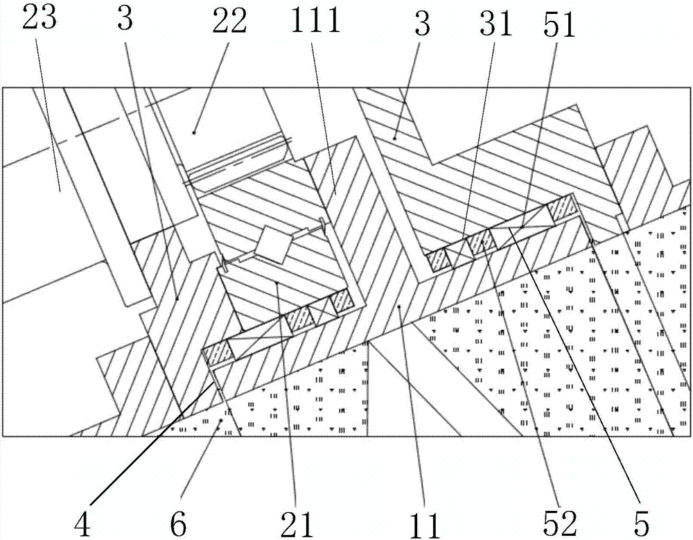
[0025] figure 1 and figure 2 The embodiment of the shield screw conveyor of the present invention is shown. The shield screw conveyor 1 includes a rotating cylinder 11, a screw shaft 12 arranged in the rotating cylinder 11 and a slag outlet 13 arranged at the rear end of the rotating cylinder 11. , the rotation of the rotating cylinder 11 drives the screw shaft 12 to transport the muck 6 backward to the slag outlet 13, and the muck 6 is discharged from the slag outlet 13. In this embodiment, the shield screw conveyor 1 includes a rotating cylinder 11 and a cylinder driving assembly 2, the rotating cylinder 11 is used to discharge the cutting muck 6, and the cylinder driving assembly 2 is used to drive the rotating cylinder 11 to rotate, The cylinder driving a...


PUM


Abstract

The invention provides a shield spiral conveyor and a shield tunneling machine. The shield spiral conveyor comprises a rotary cylinder discharging and cutting muck and a cylinder driving assembly used for driving the rotary cylinder to rotate. The cylinder driving assembly comprises a transmission bearing, an output gear and a driving part driving the output gear to rotate. The rotary cylinder is sleeved with the transmission bearing. The outer circle of the transmission bearing is fixedly connected with the rotary cylinder. The output gear is in engaged transmission with the outer circle of the transmission bearing. The shield tunneling machine comprises a shield and the shield spiral conveyor which is arranged in the shield. The shield spiral conveyor and the shield tunneling machine have the advantages of being good in stability, high in reliability, small in occupied space and the like.

Description

technical field [0001] The invention relates to the field of shield machines, in particular to a shield screw conveyor and a shield machine. Background technique [0002] The shield screw conveyor is the key component of the shield machine to realize the functions of muck transportation and earth pressure balance. The driving and sealing method of the existing shield screw conveyor mainly adopts the combination of copper sleeve and rubber seal. The transmission stability and adjustment performance of the copper sleeve seal are poor, and when the design width of the originating shaft is strict, its axial The space occupation is large, which leads to the length of the screw conveyor is too long, which is not conducive to the layout and lifting of the screw conveyor; and the rubber seal is used, the rubber is easily broken down by the high pressure of the soil, and it is easy to be driven by the rotating cylinder to rotate together. Good sealing performance cannot be guarantee...

Claims


Application Information

Patent Timeline
Patent Type & Authority Applications(China)
IPC IPC(8): E21D9/12E21D9/06
CPCE21D9/06E21D9/124
Inventor 刘飞香程永亮彭正阳廖倩刘学万佩
Owner CHINA RAILWAY CONSTR HEAVY IND
Why Eureka
Try Eureka