Piston type vacuum coaxial valve with vacuum as power air source

A technology of piston valves and coaxial valves, which is applied in the direction of valve details, valve devices, engine components, etc., to achieve the effect of high operation control cost, low power consumption, and convenient and quick operation

Pending Publication Date: 2017-08-22
南通虹登机械设备有限公司
View PDF9 Cites 1 Cited by
  • Summary
  • Abstract
  • Description
  • Claims
  • Application Information

AI Technical Summary

Problems solved by technology

The above-mentioned existing technologies must be installed horizontally when the power required in zero pressure difference or vacuum, high pressure and other environments is large, which limits the wide application of valves.

Method used


Image

  • Piston type vacuum coaxial valve with vacuum as power air source
  • Piston type vacuum coaxial valve with vacuum as power air source

Examples


Embodiment 1

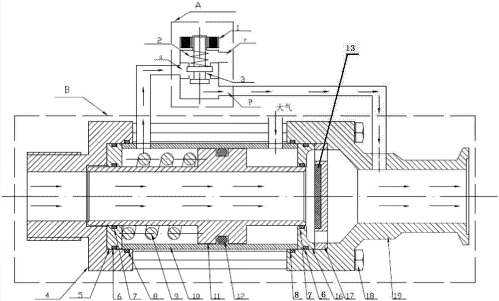
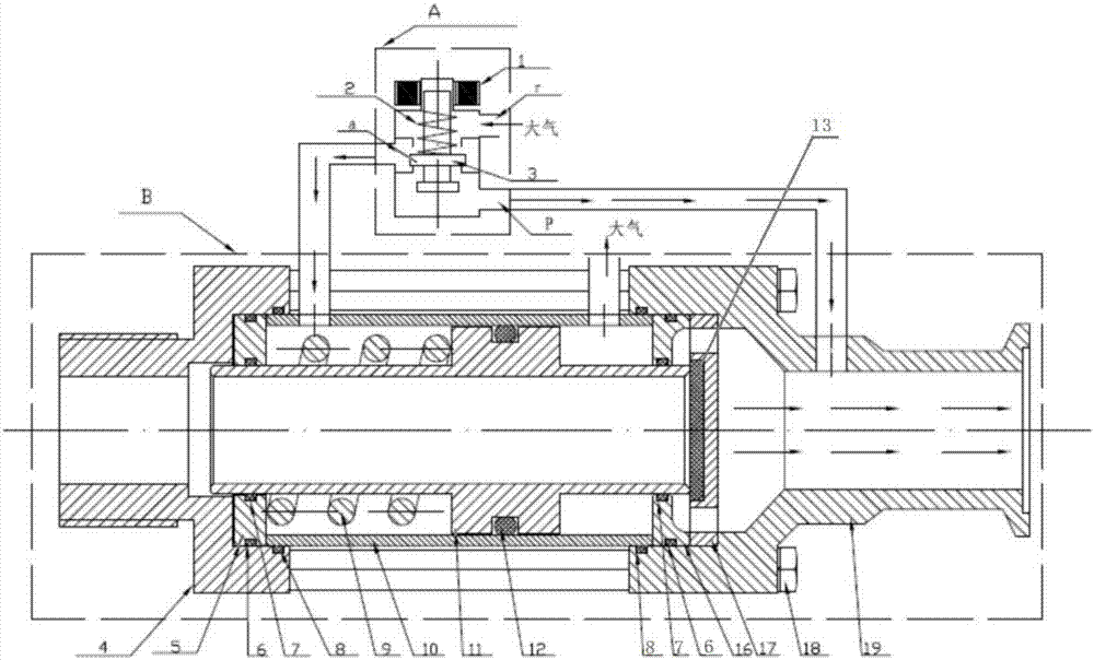
[0028] Such as figure 1 and figure 2 As shown, a piston-type vacuum coaxial valve with vacuum as a power source includes a solenoid valve part A and a coaxial valve part B: the solenoid valve part includes an electromagnetic control device; the coaxial valve part uses vacuum as a power source, including Piston type spool 11, cylinder barrel 10, left pressing block 4, right pressing block 19, left sealing block 5, right sealing block 16, sealing ring, sealing valve seat 17. Wherein, the piston type spool 11 is cylindrical, is set in the cylinder barrel 10 and can realize reciprocating movement; the two ends of the cylinder barrel 10 are equipped with sealing blocks, one on the left and one on the left, which are respectively the left sealing block 5 and the right sealing block 16, The sealing block is used to seal the gap between the piston valve core and the cylinder barrel; the outer end of the sealing block is also equipped with pressing blocks, one on the left and one on ...

Embodiment 2

[0039] refer to figure 1 and figure 2 As shown, a piston-type vacuum coaxial valve with vacuum as the power source includes a solenoid valve part and a coaxial valve part: the solenoid valve part includes an electromagnetic control device; the coaxial valve part uses vacuum as a power source, including a piston type Spool 11, cylinder barrel 10, left pressing block 4, right pressing block 19, left sealing block 5, right sealing block 16, sealing ring, sealing valve seat 17. Wherein, the piston type spool 11 is cylindrical, is set in the cylinder barrel 10 and can realize reciprocating movement; the two ends of the cylinder barrel 10 are equipped with sealing blocks, one on the left and one on the left, which are respectively the left sealing block 5 and the right sealing block 16, The sealing block is used to seal the gap between the piston valve core and the cylinder barrel; the outer end of the sealing block is also equipped with pressing blocks, one on the left and one on...


PUM


Abstract

The invention provides a piston type vacuum coaxial valve with vacuum as a power air source. The piston type vacuum coaxial valve comprises a piston type valve element, an air cylinder barrel, pressing blocks, sealing blocks, sealing rings, a sealing valve seat and an electromagnetic control device. The piston type valve element is in a barrel shape, is arranged in the air cylinder barrel in a sleeved manner and can do reciprocating motion. The sealing blocks are arranged at the two ends of the air cylinder barrel and used for sealing a sealing gap between the piston type valve element and the air cylinder barrel. The pressing blocks are arranged at the outer ends of the sealing blocks and used for pressing the sealing blocks tightly. The sealing valve seat is arranged at the outlet end of the piston type valve element and used for sealing an end opening of the piston type valve element. The sealing rings are located on mutual contacting faces of the components. By adopting the scheme, it is not needed to externally connect a power air source, the vacuum serves as the power air source, opening and closing of the coaxial valve can be achieved through a small-power two-position three-way solenoid valve, the consumed power is small, and operation is convenient and rapid.

Description

technical field [0001] The invention relates to the technical field of fluid flow valves, in particular to a piston-type vacuum coaxial valve with vacuum as a power source. Background technique [0002] Vacuum solenoid valve refers to the solenoid valve used for vacuum negative pressure system with pressure lower than normal atmospheric pressure. It is suitable for two-position on-off switching actuators in vacuum equipment pipelines. It is widely used in vacuum system pipelines in food, metallurgy and other industries. Its working principle is to use the electromagnetic induction phenomenon to control the pipeline by electromagnetic induction, and use the vacuum principle to make a vacuum structure inside the valve, which can effectively improve the working efficiency of the vacuum solenoid valve. When the medium passes through the pipeline near the vacuum solenoid valve, the medium will send information to the induction device of the vacuum solenoid valve, and the valve wi...

Claims


Application Information

Patent Timeline
IPC IPC(8): F16K31/122F16K31/06
CPCF16K31/06F16K31/122
Inventor 管建新李雷李建清
Owner 南通虹登机械设备有限公司
Why Eureka
Try Eureka