Structure capable of facilitating mounting of textile machine

A technology for installing structures and textile machines, applied in the direction of supporting machines, mechanical equipment, machine tables/supports, etc., can solve problems such as inability to stabilize equipment, waste of time and energy, and no operational effect, so as to ensure efficiency, practicability, and saving The effect of time and effort, good stabilization effect

Inactive Publication Date: 2017-08-22
YANCHENG XUER TEXTILE
View PDF0 Cites 2 Cited by
  • Summary
  • Abstract
  • Description
  • Claims
  • Application Information

AI Technical Summary

Problems solved by technology

[0004] (1) There is not a good installation effect of the textile machine, which leads to the inability to provide a good installation convenience during use, which brings a lot of inconvenience, wastes a lot of time and energy, and cannot guarantee the use of the device during use Effect;
[0005] (2) There is no good operation effect, and it cannot provide users with a good use convenience, resulting in no good use effect during the operation process, and cannot effectively adjust and handle the equipment;
[0006] The equipment cannot be effectively stabilized, resulting in no good stabilization effect during the use of the equipment, which brings inconvenience. At the same time, the efficiency and practicability of the equipment during use cannot be guaranteed

Method used


Image

  • Structure capable of facilitating mounting of textile machine
  • Structure capable of facilitating mounting of textile machine

Examples


Embodiment Construction

[0021] The following will clearly and completely describe the technical solutions in the embodiments of the present invention with reference to the accompanying drawings in the embodiments of the present invention. Obviously, the described embodiments are only some, not all, embodiments of the present invention.

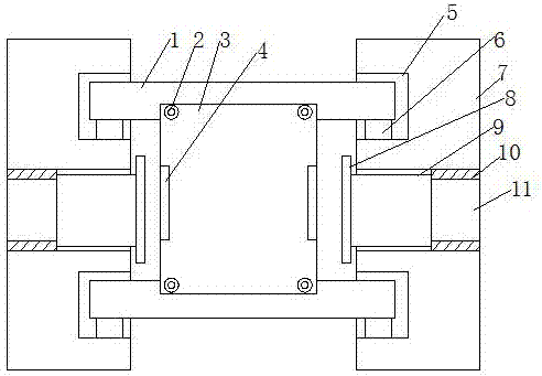
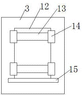
[0022] refer to Figure 1-2 , a convenient installation structure for the textile machine, including a support rod 7, the number of the support rods 7 is two, and the support rods 7 are installed in parallel in pairs, and both sides of one end of the support rods 7 are provided with clamping grooves 5, which are clamped One end of the groove 5 is provided with a fixed block 6, and a connecting shaft 1 is installed between two fixed blocks 6, and a mounting plate 3 is installed between the connecting shafts 1 through a connecting piece 2, and the two ends of the mounting plate 3 are provided with clamps. Connect the falcon 4, the inner cavity of the support rod 7 is p...


PUM


Abstract

The invention discloses a convenient installation structure for a textile machine, which includes a support rod. The number of the support rods is two, and the two support rods are installed in parallel. Both sides of one end of the support rods are provided with clamping grooves. One end of the clamping groove is provided with a fixed block, and a connecting shaft is installed between two of the fixed blocks, and a mounting plate is installed between the connecting shafts through a connecting piece, and both ends of the mounting plate are provided with There is a clamping falcon, the inner cavity of the support rod is provided with a regulator, the outer end of the regulator is provided with a protective end plate, one end of the regulator is provided with a transmission rod, and one end of the transmission rod extends to the support rod The outer end of the transmission rod is provided with a processing plate at one end. The present invention has a good installation effect of the textile machine, can provide a good installation convenience during use, brings a lot of convenience, saves a lot of time and energy, and can ensure the use effect of the device during use.

Description

technical field [0001] The invention relates to the technical field of textiles, in particular to a convenient installation structure for textile machines. Background technique [0002] The original meaning of textile is taken from the general term of spinning and weaving, but with the continuous development and improvement of the textile knowledge system and subject system, especially after the emergence of non-woven textile materials and three-dimensional composite weaving technologies, the current textile is not only a traditional Hand spinning and weaving also include garment, industrial and decorative textiles produced by non-woven technology, modern three-dimensional weaving technology, and modern electrostatic nano-netting technology. Therefore, modern textile refers to a multi-scale structure processing technology of fibers or fiber aggregates. Ancient Chinese textile and printing and dyeing technology has a very long history. As early as the primitive society, the ...

Claims


Application Information

Patent Timeline
Patent Type & Authority Applications(China)
IPC IPC(8): F16M11/04F16M11/18
CPCF16M11/041F16M11/18
Inventor 惠刚惠开兵郑玲玲殷瑞明张兴群刘国亮殷一文
Owner YANCHENG XUER TEXTILE
Why Eureka
Try Eureka