Dual-polarized antenna and antenna array

A dual-polarized antenna and radiating arm technology, applied in antennas, independent antenna unit combinations, radiating element structures, etc., can solve problems such as large volume and narrow frequency band, and achieve reduced aperture area, reduced peripheral size, and improved station. The effect of wave width

Pending Publication Date: 2017-08-22
ANPULUO SUZHOU COMM TECH CO LTD
View PDF10 Cites 1 Cited by
  • Summary
  • Abstract
  • Description
  • Claims
  • Application Information

AI Technical Summary

Problems solved by technology

However, the existing dual-polarized antenna not only has a narrow frequency band, but also has a large volume

Method used


Image

  • Dual-polarized antenna and antenna array
  • Dual-polarized antenna and antenna array
  • Dual-polarized antenna and antenna array

Examples


Embodiment 1

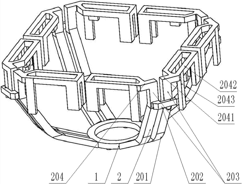
[0022] A dual-polarized antenna, such as the attached figure 1 As shown, it includes: a vibrator 2 and a base 1, the vibrator 2 is connected to the base 1; the vibrator 2 has four pairs, and the four pairs of the vibrator 2 are arranged adjacent to each other to form a mutually orthogonal dual polarization unit , each pair of oscillators 2 includes a balun arm 201, a feeding arm 202, a transmission arm 203, and a radiation arm 204; The arm 202 is located between the balun arm 201 and the transmission arm 203, the transmission arm 203 is located between the feeding arm 202 and the radiation arm 204, and the lower ends of the four balun arms 201 of the vibrator 2 are connected to the base 1, The radiation arm 204 includes a radiation arm a2041, a radiation arm b2042, and a radiation arm c2043; the radiation arm a2041 is at the top of the transmission arm 203, the radiation arm b2042 is located at the end of the radiation arm a2041, and the radiation arm c2043 is located on the r...

Embodiment 2

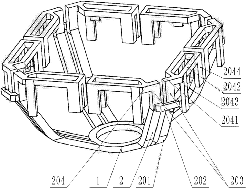
[0025] A dual-polarized antenna, such as the attached figure 2 As shown, the rest of the features are the same, but the radiation arm 204 also includes a radiation arm d2044, the radiation arm d2044 is arranged at the end of the radiation arm b2042 (that is, the end away from the transmission wall), and the radiation arm d2044 Extend along the vertical direction of the radial arm b2042. The radiation arm c2043 and / or the radiation arm d2044 extend toward the base 1 . By adopting such a structural design, the volume of the vibrator 2 is reduced. The orthographic projection of the radiation arm b2042 is a rectangle. The radiation arm a2041 is connected to one end of the radiation arm b2042, and the radiation arm d2044 is connected below the other end of the radiation arm b2042.

[0026] The transmission arms 203 of the vibrator 2 are parallel to each other or extend in a direction perpendicular to the base 1 within an angle range of plus or minus 30 degrees.

Embodiment 3

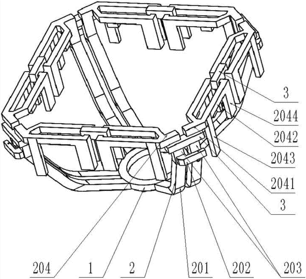
[0028] A dual-polarized antenna, such as the attached image 3 As shown, a fixing member 3 is provided between the transmission arms 203 in each pair of dipoles 2, and a fixing member 3 is provided between the radiation arms b2042 and / or radiation arms d2044 of two adjacent dipoles 2, The fixing member 3 is made of insulating material (such as plastic). The arrangement of the fixing member 3 not only ensures the structural strength of the vibrator 2 , but also ensures the size of the vibrator 2 .

[0029] An antenna array including the above-mentioned dual-polarized antenna as a low-frequency unit, as attached Figure 4 As shown, it also includes a high-frequency unit 4 and a reflector 5. A high-frequency unit 4 operating in the high-frequency range is arranged in the low-frequency unit, and a high-frequency unit 4 is also arranged between the two low-frequency units. Several high-frequency units 4 and low-frequency units are vertically arranged to form an antenna array. Th...


PUM


Abstract

The invention relates to a dual-polarized antenna. The dual-polarized antenna comprises a reflecting plate, oscillators and a base, four pairs of oscillators are arranged in an adjacent manner in pairs to form dual-polarized units orthogonal to each other, each pair of oscillators include balun arms, a feeding arm, transmission arms and radiating arms, the transmission arms are located between the feeding arm and the radiating arms, the radiating arms comprise radiating arms a, radiating arms b and radiating arms c, the radiating arms a are arranged at the top ends of the transmission arms, the radiating arms b are located at the bottom ends of the radiating arms a, the radiating arms a and the radiating arms b of the four pairs of oscillators are projected in the square shape on the reflecting plate, the radiating arms c are located on the radiating arms b, and the radiating arms c extend along the vertical direction of the radiating arms b. An antenna array comprises the dual-polarized antennas as low-frequency units, the antenna array also comprises high-frequency units and a reflecting plate, and the low-frequency units and the high-frequency unit are vertically arranged on the reflecting plate at intervals. By employing the new antenna structure, the frequency band is wide, the size is small, and the high-frequency influence is small.

Description

technical field [0001] The invention relates to a novel ultra-wideband dual-polarized antenna and an antenna array, belonging to the technical field of mobile communication base station antennas. Background technique [0002] With the development of mobile communications, the requirements for antennas are getting higher and higher, and the demand for multi-frequency and multi-port antennas is increasing. There is an increasing demand for miniaturized antennas. However, the existing dual-polarized antenna not only has a narrow frequency band, but also has a large volume. When such dual-polarized antennas form an antenna array, such low-frequency dual-polarized antennas have a great impact on the radiation of high-frequency antennas. Such as the Chinese patent, the application number is CN01806627.5, the dual-polarization dipole antenna array is fed in relation to two opposite parallel dipoles of a dipole square, that is, the power cable leads to a Feed point on a dipole; f...

Claims


Application Information

Patent Timeline
Patent Type & Authority Applications(China)
IPC IPC(8): H01Q1/36H01Q19/10H01Q21/30
CPCH01Q1/36H01Q19/106H01Q21/30
Inventor 罗英涛
Owner ANPULUO SUZHOU COMM TECH CO LTD
Why Eureka
Try Eureka