Dielectric substrate integrated waveguide slot array

A technology for integrating waveguides and dielectric substrates, applied to slot antennas, antenna arrays, specific array feeding systems, etc., can solve the problems of heavy weight, complex processing, and large size of metal waveguides to reduce weight and improve side lobes , Improve the effect of positioning accuracy

Pending Publication Date: 2018-12-28
FUDAN UNIV
View PDF10 Cites 5 Cited by
  • Summary
  • Abstract
  • Description
  • Claims
  • Application Information

AI Technical Summary

Problems solved by technology

However, due to the large size, heavy weight and complex proc

Method used


Image

  • Dielectric substrate integrated waveguide slot array
  • Dielectric substrate integrated waveguide slot array
  • Dielectric substrate integrated waveguide slot array

Examples


Embodiment Construction

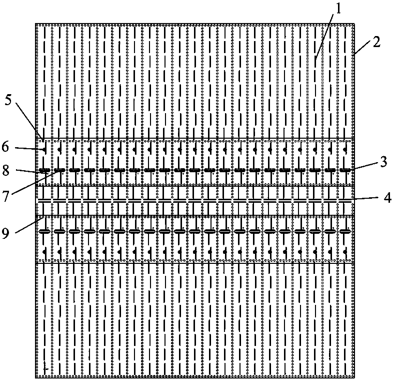
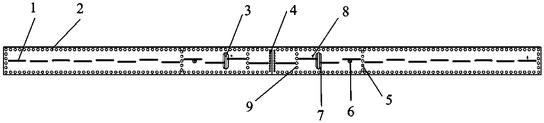
[0020] figure 1 A top view of the structure of the array. The main structure of the array is formed by pressing two double-sided copper-clad dielectric plates. The upper dielectric plate constitutes the main structure of the radiation waveguide, and the feed waveguide is composed of the lower dielectric plate. The structure of the array is from top to bottom: open in the radiation waveguide The radiation gap 1 on the copper foil on the upper layer of the waveguide, together with the upper and lower layers of copper foil on the upper dielectric plate, constitutes the conductive through holes 2 and 4 of the cavity structure of the radiation waveguide, and the coupling gap 3 opened on the copper foil of the lower layer of the radiation waveguide is opened on the feeder The coupling slot 7 on the upper copper foil of the electric waveguide, the tuning hole 8 next to the coupling slot of the feeding waveguide, together with the upper and lower layers of copper foil on the lower die...


PUM


Abstract

The invention belongs to the technical field of radar antennas, in particular to a substrate integrated waveguide slot antenna array. The array antenna of the invention is composed of a plurality of waveguide slot subarrays arranged side by side, and the substrate integrated waveguide slot antenna array is composed of two copper-coated dielectric plates. The upper layer is dielectric radiation waveguide and the lower layer is dielectric feed waveguide. The coupling slot is used to feed the radiation waveguide and the feed waveguide, and the lower layer is used to feed the feed waveguide through the coaxial joint. The coupling slot is located in the middle of the radiation waveguide and perpendicular to the radiation slot to reduce the direct coupling between the two, and a harmonic slot islocated next to the coupling slot of the feed waveguide to adjust the impedance matching. The antenna array can be swept in a direction perpendicular to the waveguide line and scanned mechanically ina direction along the waveguide line. The antenna array of the invention is light in weight, small in size, strong in anti-interference ability and high in positioning accuracy.

Description

technical field [0001] The invention belongs to the technical field of radar antennas, in particular to a dielectric substrate integrated waveguide slot array. Background technique [0002] The waveguide slot antenna has been widely used in the fields of communication and radar because of its excellent characteristics such as low loss, high gain, low profile and stable structure. There are various forms of waveguide slots, commonly used are wide-side offset slots, narrow-side inclined slots, ridge waveguide double slots, etc. However, due to the large size, heavy weight and complex processing of metal waveguides, its application range is limited. [0003] The substrate-integrated waveguide slot array not only inherits the advantages of the traditional metal waveguide slot array, but also has the advantages of convenient processing, light weight and small size, so it can be applied in many occasions that do not require high power but are sensitive to size, weight and cost. ...

Claims


Application Information

Patent Timeline
IPC IPC(8): H01Q1/38H01Q1/50H01Q13/10H01Q21/00H01Q21/06H01Q25/02
CPCH01Q1/38H01Q1/50H01Q13/106H01Q21/0006H01Q21/064H01Q25/02
Inventor 尹卫爽关放梁修业张喆刘晓晗资剑
Owner FUDAN UNIV
Why Eureka
Try Eureka