Circularly polarized antenna element

A technology of circularly polarized antennas and feeders, which is applied in the directions of antennas, antenna couplings, and antenna grounding devices. It can solve problems such as limited ability to widen bandwidth, failure to meet ultra-wideband requirements, and large coupling between two ports to reduce cross-polarization. , realizing ultra-wideband and easy-to-debug design, and improving the effect of isolation

Active Publication Date: 2022-04-05
HUBEI SANJIANG SPACE XIANFENG ELECTRONICS&INFORMATION CO LTD
View PDF10 Cites 0 Cited by
  • Summary
  • Abstract
  • Description
  • Claims
  • Application Information

AI Technical Summary

Problems solved by technology

Considering the limitations of the carrier installation environment, most of the existing sunken-mounted missile-borne communication antennas use the form of microstrip patch antennas, and the conventional methods of widening the working frequency bandwidth of microstrip patch antennas include slot coupling feeding, multiple Layer coupling feeding, L-shaped probe feeding, etc., but these conventional methods have the following problems: 1. The ability to widen the bandwidth is limited, and it cannot meet the ultra-wideband requirements; 2. In the design and debugging of dual-port circular polarization, especially Like an L-shaped probe feed, the coupling between the two ports is larger

Method used


Image

  • Circularly polarized antenna element
  • Circularly polarized antenna element
  • Circularly polarized antenna element

Examples


Embodiment Construction

[0031] In order to make the object, technical solution and advantages of the present invention clearer, the present invention will be further described in detail below in conjunction with the accompanying drawings and embodiments. It should be understood that the specific embodiments described here are only used to explain the present invention, not to limit the present invention. In addition, the technical features involved in the various embodiments of the present invention described below can be combined with each other as long as they do not constitute a conflict with each other.

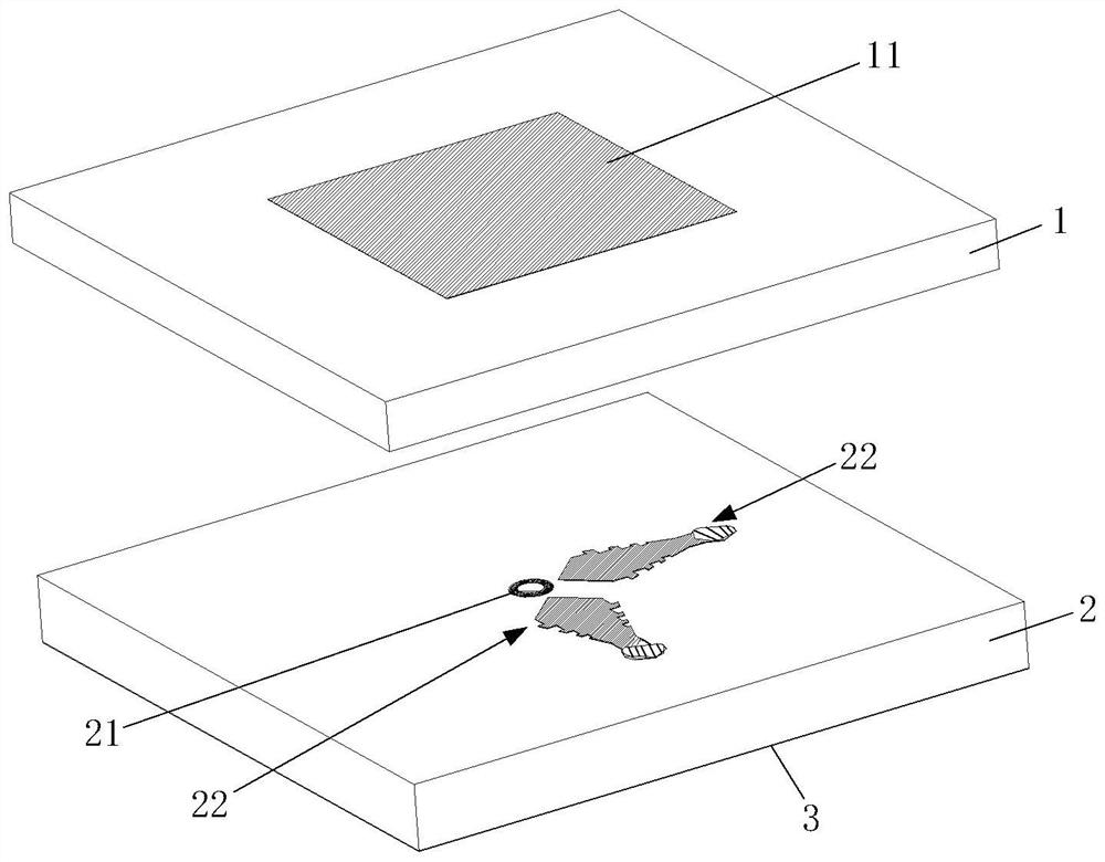
[0032] figure 1 is an exploded schematic diagram of a circularly polarized antenna element provided by an embodiment of the present invention, as shown in figure 1 As shown, the circularly polarized antenna element includes a first dielectric substrate 1 , a second dielectric substrate 2 and a ground plate 3 stacked in sequence.

[0033] The top surface of the first dielectric substrate 1 has ...


PUM

PropertyMeasurementUnit
sizeaaaaaaaaaa
diameteraaaaaaaaaa
sizeaaaaaaaaaa

Abstract

The invention discloses a circularly polarized antenna element, and belongs to the technical field of antennas. The circularly polarized antenna element comprises a first dielectric substrate, a second dielectric substrate and a grounding plate which are stacked in sequence. The top surface of the first dielectric substrate is provided with a radiation patch. The second dielectric substrate is provided with a metal wafer and two L-shaped feed structures, the second dielectric substrate is provided with a first through hole and a plurality of second through holes, each L-shaped feed structure comprises a feed probe and a feed line, each feed probe vertically penetrates through the second dielectric substrate and the grounding plate, each feed line comprises a bonding pad part, a connecting part and a fan-shaped part, and the bonding pad part is connected with the connecting part. The small ends of the fan-shaped parts are connected with the bonding pad parts through the connecting parts, and the edges of the two sides of each fan-shaped part are provided with a plurality of notches which are symmetrically arranged along the central axis of the fan-shaped part. According to the circularly polarized antenna element provided by the embodiment of the invention, the coupling effect between the two feeder lines can be effectively weakened, the standing wave bandwidth of the antenna can be effectively improved, and an ultra wide band is realized.

Description

technical field [0001] The invention belongs to the technical field of antennas, and more specifically relates to a circularly polarized antenna element. Background technique [0002] With the rapid development of wireless communication systems and missile-borne communication fields, missile-borne communication systems have put forward more and more demands and high requirements for the performance of antennas in communication fields such as missile-to-ground, missile-to-missile, and missile-to-satellite based on actual use requirements. . [0003] In the use environment and requirements of some missile-borne communication systems, the missile-borne communication antenna is required to have an ultra-wide operating frequency bandwidth and a circular polarization working mode. Considering the limitations of the carrier installation environment, most of the existing sunken-mounted missile-borne communication antennas use the form of microstrip patch antennas, and the conventio...

Claims


Application Information

Patent Timeline
Patent Type & Authority Applications(China)
IPC IPC(8): H01Q1/38H01Q1/48H01Q1/50H01Q1/52H01Q15/24
CPCY02A90/10
Inventor 柳灿雄潘丹丹谢修进
Owner HUBEI SANJIANG SPACE XIANFENG ELECTRONICS&INFORMATION CO LTD
Why Eureka
Try Eureka