
A absorbing reflective array control device for feeding image beams in a compact field anechoic chamber

A control device and compact field technology, applied in the direction of antennas, electrical components, etc., can solve the difficulty and cost of adding reflective surfaces and feed source foundations, limit the application of feed source image interference suppression technology, affect the installation or daily maintenance of process equipment, etc. , to achieve the effect of improving engineering realizability, improving test accuracy, increasing complexity and manufacturing cost

Active Publication Date: 2020-07-03
BEIHANG UNIV
View PDF7 Cites 0 Cited by
  • Summary
  • Abstract
  • Description
  • Claims
  • Application Information

AI Technical Summary

Problems solved by technology

However, for the compact field of indoor work, if the ground is uneven, it will affect the installation of process equipment or daily maintenance, and increase the difficulty and cost of integrating reflective surfaces and feed source foundations
This greatly limits the application of feed image interference suppression technology

Method used


Image

  • A absorbing reflective array control device for feeding image beams in a compact field anechoic chamber
  • A absorbing reflective array control device for feeding image beams in a compact field anechoic chamber
  • A absorbing reflective array control device for feeding image beams in a compact field anechoic chamber

Examples


Embodiment Construction

[0039] The present invention will be further described below in conjunction with the accompanying drawings and specific embodiments.

[0040] A preferred embodiment of the present invention:

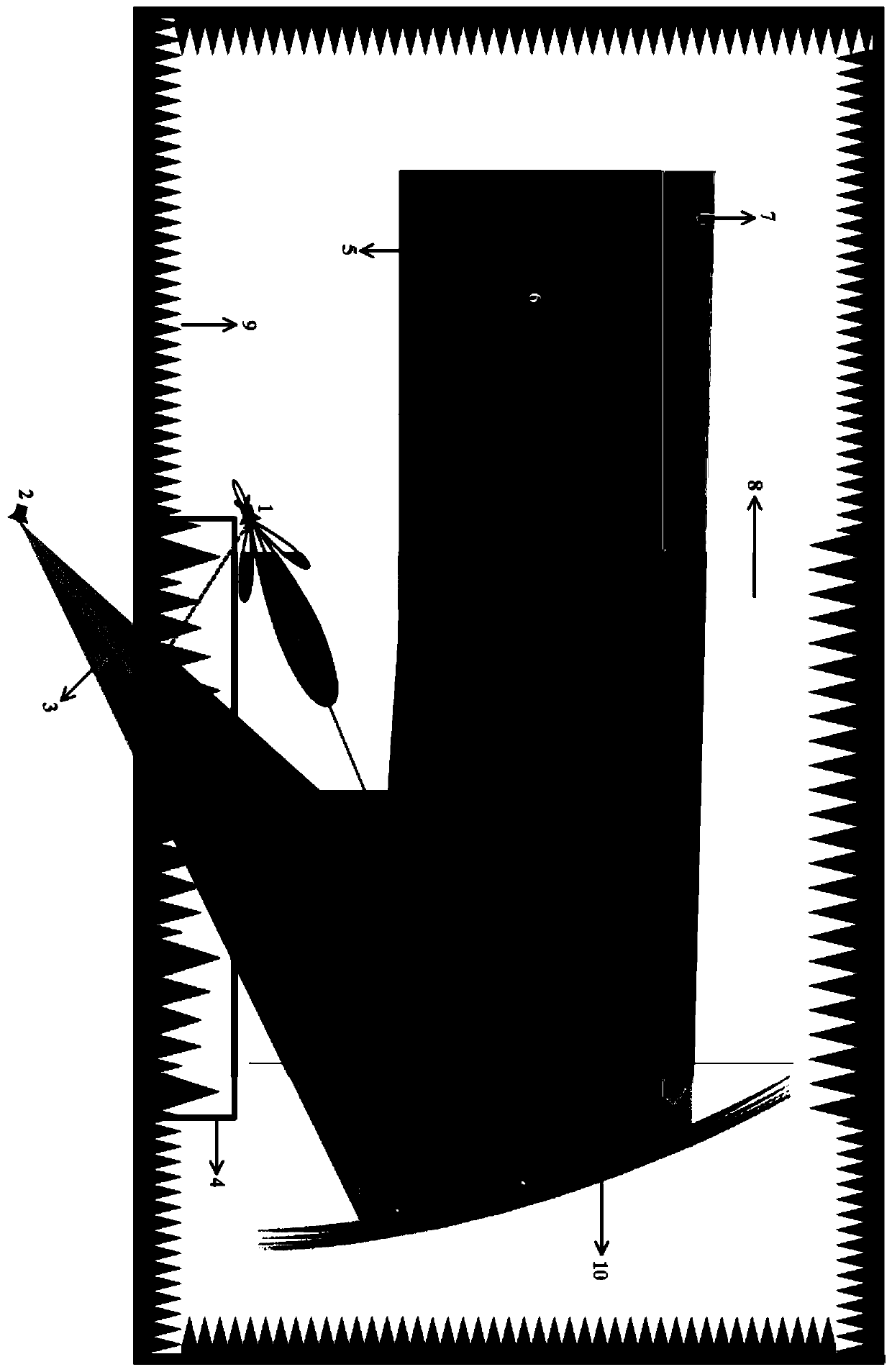
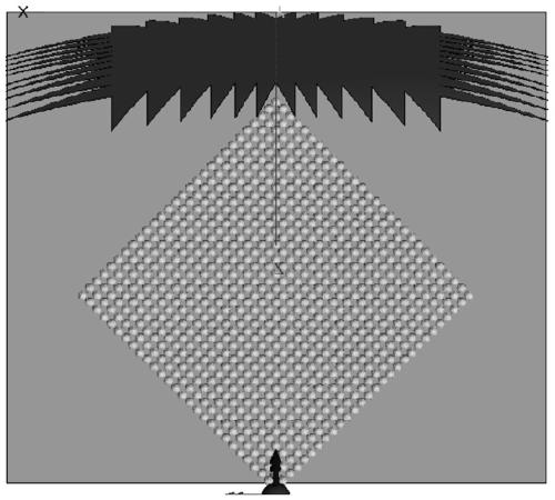
[0041] Such as figure 1 The schematic diagram of the absorbing reflective array control device for the feed image beam in the compact field anechoic room is shown, including feed 1, image feed 2, image irradiation beam 3, absorbing reflective array 4, quiet zone beam 5, quiet zone 6, mirror image Reflected beam 7 , mirror image reflected beam 8 adjusted by the absorbing reflective array, absorbing material 9 and compact field reflective surface 10 . Reflecting surface size: 16.16m×12.385m, focal length 14.4m, virtual apex elevation 1.026m, reflective surface with 10 left and right serrations, 12 upper and lower teeth, length of left and right teeth 3.2m, length of upper and lower teeth 2.4m, feed source The height is 2.0m, and the quiet zone is 18.0m away from the mouth surface on the ...


PUM


Abstract

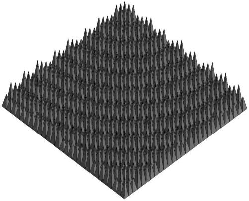
The invention discloses a wave-absorbing reflection array control device for feeding mirror beams in a compact field anechoic room. The device is mainly composed of a compact field reflecting surface, a feed source, a microwave dark room and a mirror beam control system. By controlling the height of each absorbing material unit in the area, the alignment of the outgoing wavefront is adjusted to a direction away from the quiet zone, the purpose is to suppress the interference of the area reflection clutter on the quiet zone, such as the mirror reflection of the feed source. The device is determined by parameters such as operating frequency, feed source height, quiet zone height and number of Fresnel wave bands. The low-frequency image beam control of the present invention has broadband reconfigurability, and realizes the broadband work of the low-frequency darkroom through the continuous control of the height of the reflection unit in the image area.

Description

technical field [0001] The present invention relates to the layout of absorbing materials in an anechoic chamber in a compact field, and in particular to a control of a reflective reflective array for feed mirroring, which is mainly used in low-frequency work tests in a compact field to improve low-frequency antenna patterns or radar targets RCS tests the performance of the required quiet zone plane wavefield. Background technique [0002] With the development of advanced meter wave radar and stealth weapons, the confrontation between anti-stealth and stealth technology in the meter wave band is intensifying, and the demand for meter wave radar antenna and stealth target meter wave characteristic testing is becoming increasingly urgent. The traditional outdoor far field has insurmountable defects in meter wave testing, such as electromagnetic spectrum crowding, ground image and multipath interference. Although the compact field technology plays an irreplaceable and importan...

Claims


Application Information

Patent Timeline
Patent Type & Authority Patents(China)
IPC IPC(8): H01Q17/00
CPCH01Q17/007
Inventor 李志平武建华王正鹏霍鹏
Owner BEIHANG UNIV
Learn More