Rapid-disassembly batching device with telescopic batching roller

A cloth roll and cloth rolling technology, which is applied in the field of textile rolling, can solve unreasonable and cumbersome problems, and achieve the effect of improving work efficiency and saving resources

Active Publication Date: 2017-08-25
湖州南浔临港新农村建设发展有限公司
View PDF6 Cites 3 Cited by
  • Summary
  • Abstract
  • Description
  • Claims
  • Application Information

AI Technical Summary

Problems solved by technology

[0004] For example, the Chinese patent discloses the patent number of "a reel device for textile machinery": 201520982120.6. In this patent, the cloth is pressed by the pressing plate to avoid the deviation of the cloth. However, it is too cumbersome to disassemble the pressing plate every time before rolling the cloth. , and it uses a buckle to realize the quick release of the roll, but the first roll still needs to be transported with the textile, which is very unreasonable

Method used


Image

  • Rapid-disassembly batching device with telescopic batching roller
  • Rapid-disassembly batching device with telescopic batching roller
  • Rapid-disassembly batching device with telescopic batching roller

Examples


Embodiment 1

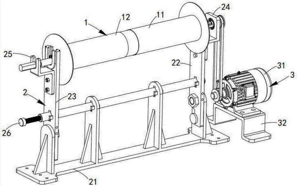
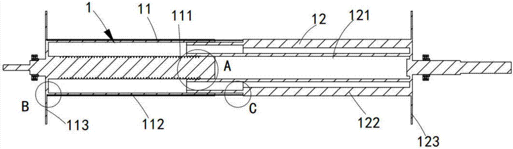
[0047] Such as figure 1 and figure 2 As shown, a retractable and quick-release cloth rolling device for the cloth rolling roller, including:

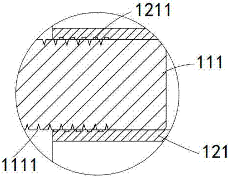
[0048] Cloth rolling roller 1, the cloth rolling roller 1 includes a first roller 11 and a second roller 12, and the first roller 11 and the second roller 12 respectively pass through the first main shaft 111 and the second main shaft 121 Concentric sliding socket;

[0049] Frame 2, the frame 2 is used to support the cloth rolling roller 1, it includes a base 21, and a first bracket 22 and a second bracket 23 respectively symmetrically hinged on both sides of the base 21, and it also includes a The driving mounting plate 24 fixedly connected to the first bracket 22 and the limiting plate 25 fixedly connected to the second bracket 23;

[0050] The driving assembly 3, the driving assembly 3 is arranged on one side of the frame 2, which is located on one side of the first roller 11, and drives the first roller 11 to rotate, and drives th...

Embodiment 2

[0074] Figure 11 It is a structural schematic diagram of Embodiment 2 of a retractable and quick-release cloth rolling device of the present invention; Figure 11 As shown, the components that are the same as or corresponding to those in the first embodiment are marked with the corresponding reference numerals in the first embodiment. For the sake of simplicity, only the differences from the first embodiment will be described below. This embodiment two and figure 1 The difference of the shown embodiment one is:

[0075] like Figure 11 As shown, a retractable and quick-release cloth roll device also includes a transfer trolley 4, which is arranged parallel to the length direction of the frame 2, and is used to transfer rolled textiles.

[0076] It should be noted that after the cloth roll 1 has finished winding the cloth, the positioning roller 26 is pulled out, the first bracket 22 and the second bracket 23 are rotated so that the cloth roll 1 is placed on the transfer tr...


PUM


Abstract

The invention discloses a rapid-disassembly batching device with a telescopic batching roller. A first roller body and a second roller body are connected in sleeved and sliding manners through threads on a first main shaft and a second main shaft which are located in the middle, so that when the first roller body conducts initial cloth batching, the second roller body can slide outwards in the axial direction, and the axial length of the first roller body and the second roller body is increased; and in this way, even if cloth deviates, a certain length margin is provided to guarantee that when the cloth is slantly inclined, no wrinkle is generate. Meanwhile, after cloth batching is completed, the first roller body and the second roller body can be rapidly separated and do not need to be conveyed along with the cloth and hence, the technical problem that the cloth deviates, exceeds the edge of a cloth roller and generates wrinkles is solved, the technical problem of rapid separation of the batching roller and the cloth is also solved, the work efficiency is improved, and resources are greatly saved.

Description

[0001] machine technology [0002] The invention relates to the technical field of textile rolling, in particular to a retractable and quick-release cloth rolling device for a cloth rolling roller. Background technique [0003] Due to the increasing competitive pressure in all walks of life, production efficiency is becoming more and more important for various industries, including the textile industry. The existing technology of textile machinery has a relatively primitive reel structure. In the process, it is necessary to manually adjust the textiles to avoid skewing and uneven winding of the cloth when the cloth is rolled up, and wrinkles beyond the edge of the cloth roller, and after the cloth is rolled, it is necessary to transport the roll and the textile together, which is extremely inconvenient , while increasing the difficulty in the conveying process, and it is necessary to prepare an extremely large number of rolls as backup, resulting in a waste of resources. [0...

Claims


Application Information

Patent Timeline
Patent Type & Authority Applications(China)
IPC IPC(8): B65H75/22
CPCB65H75/22B65H2701/174
Inventor 王会文
Owner 湖州南浔临港新农村建设发展有限公司
Why Eureka
Try Eureka