Special tunnel lining deformation monitoring method
A deformation monitoring and tunneling technology, applied in measurement devices, instruments, optical devices, etc., can solve problems such as large workload and low efficiency, and achieve the effects of fast acquisition speed, improved work efficiency, and high measurement accuracy
- Summary
- Abstract
- Description
- Claims
- Application Information
AI Technical Summary
Problems solved by technology
Method used
Image
Examples
Embodiment 1
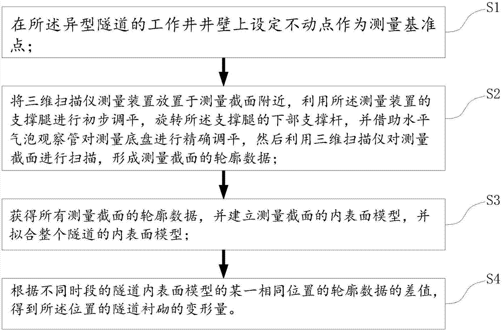
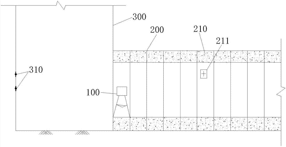
[0036] see figure 1 and figure 2 , the special-shaped tunnel lining 200 deformation monitoring method provided by the present invention includes the following steps:
[0037] S1. Set a fixed point on the wall of the working shaft 300 of the special-shaped tunnel as the measurement reference point 310 . The three-dimensional coordinates of the reference point 310 serve as a reference point for the profile data of the section of the tunnel lining 200 . During tunnel construction, a vertical working shaft 300 will be set, and the deformation of the shaft wall of the working shaft 300 is generally small and negligible. Therefore, the reference point 310 can be set on the shaft wall of the working shaft 300 .
[0038] S2. Place the three-dimensional scanner measurement device 100 near the measurement section 210, use the support legs of the measurement device 100 to perform preliminary leveling, and rotate the lower support rod of the support legs, and use the horizontal bubble ...
Embodiment 2
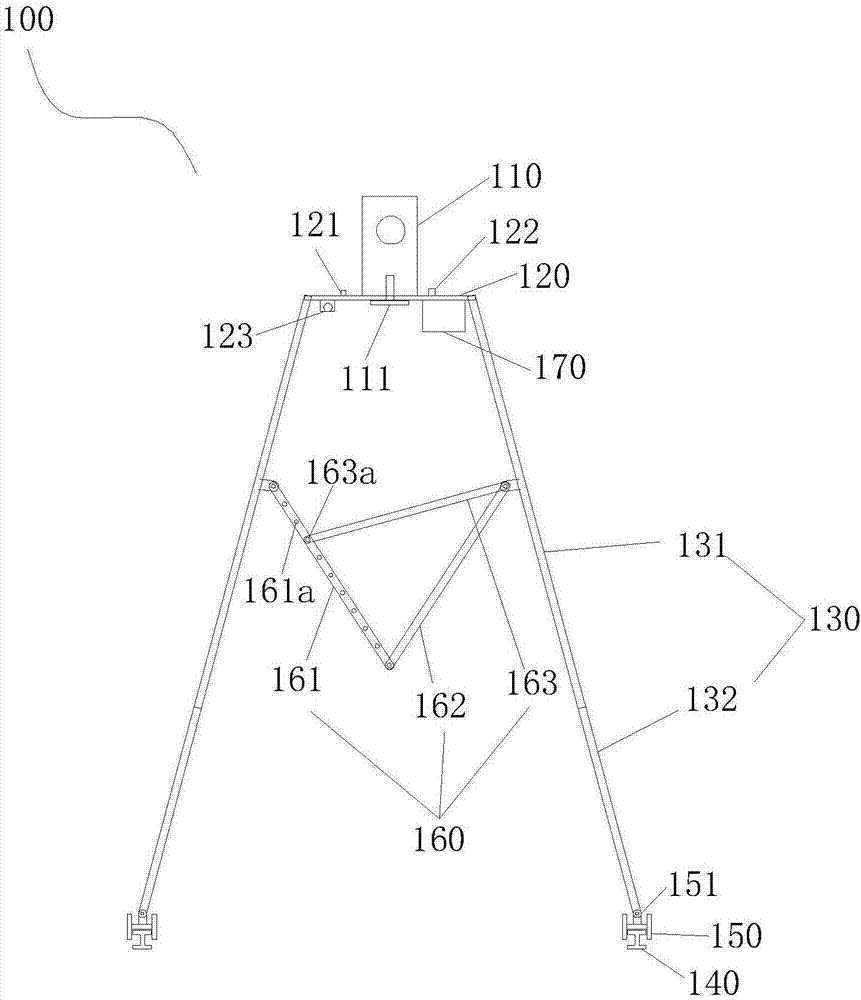
[0045] refer to image 3 and Figure 4 , the present invention also provides a three-dimensional scanning measurement device 100 suitable for monitoring deformation of special-shaped tunnel lining, including a three-dimensional scanner 110 , a measurement chassis 120 and support legs 130 . Wherein, the three-dimensional scanner 110 is fixedly connected with the measurement chassis 120 by connecting bolts 111. As an example, the measurement chassis 120 is a steel plate with a length, width and thickness of 30cm×30cm×0.5cm respectively, and a hole is left in the center of the measurement chassis 120, and the diameter ratio of the hole is The outer diameter of the connecting bolt 111 of the three-dimensional scanner 110 is 1-2 cm larger. The measurement chassis 120 is provided with a horizontal bubble observation tube 121 for judging whether the measurement chassis 120 is level.
[0046] The supporting leg 130 is hinged to the measuring chassis 120 , here is a one-way hinge, an...
PUM
 Abstract
Description
Claims
Application Information
 - R&D
- Intellectual Property
- Life Sciences
- Materials
- Tech Scout
- Unparalleled Data Quality
- Higher Quality Content
- 60% Fewer Hallucinations
Browse by: Latest US Patents, China's latest patents, Technical Efficacy Thesaurus, Application Domain, Technology Topic, Popular Technical Reports.
© 2025 PatSnap. All rights reserved.Legal|Privacy policy|Modern Slavery Act Transparency Statement|Sitemap|About US| Contact US: help@patsnap.com


