Optical fiber laser and liquid cooling plate thereof

A fiber laser and liquid cooling plate technology, applied in the field of lasers, can solve the problems of high cost and low production efficiency, and achieve the effects of saving costs, improving production efficiency and improving versatility

Active Publication Date: 2017-08-25
SU ZHOU MAXPHOTONICS CO LTD
View PDF5 Cites 6 Cited by
  • Summary
  • Abstract
  • Description
  • Claims
  • Application Information

AI Technical Summary

Problems solved by technology

[0004] The present invention aims at the technical problems in the prior art that when it is necessary to produce fiber lasers with different output powers, it is necessary to produce a variety of liquid cooling plates of different sizes, the cost is high, and the production efficiency is low, and a fiber laser and its liquid cooling plate are provided.

Method used


Image

  • Optical fiber laser and liquid cooling plate thereof
  • Optical fiber laser and liquid cooling plate thereof
  • Optical fiber laser and liquid cooling plate thereof

Examples


Embodiment 1

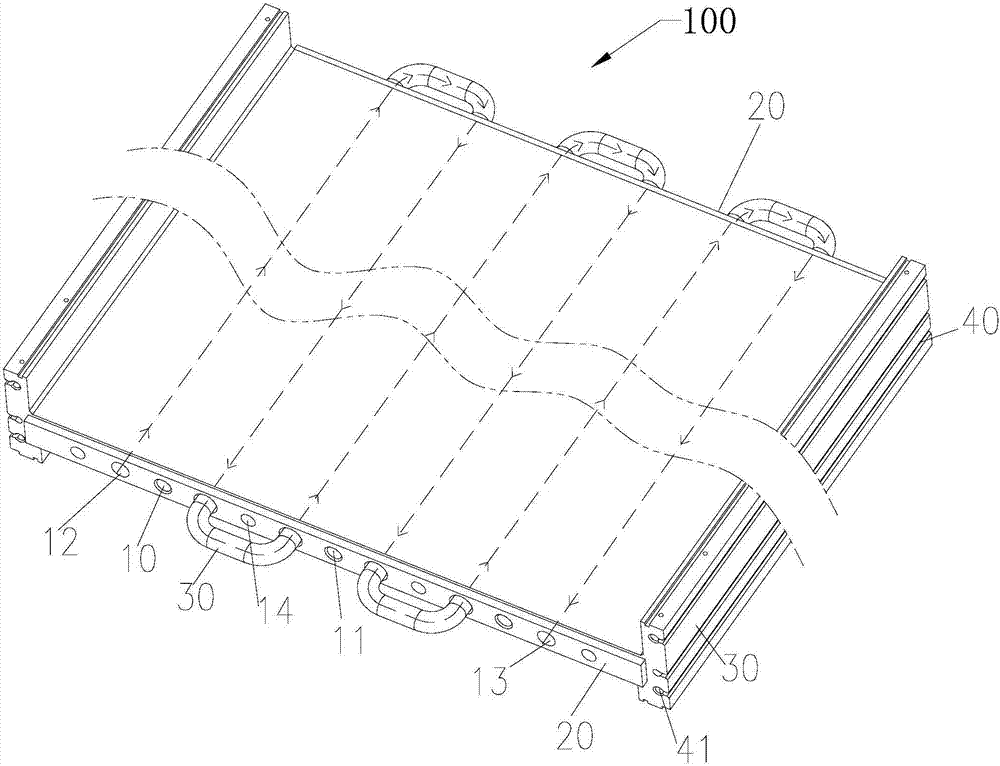
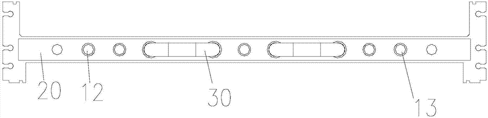
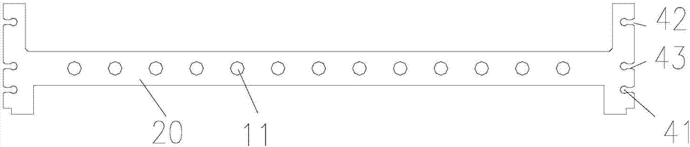
[0030] figure 1 It is a schematic structural diagram of the liquid cold plate of the embodiment of the present invention. like figure 1 As shown, the liquid cooling plate 100 for fiber laser, the liquid cooling plate 100 is used for heat dissipation of the optical path module and circuit module of the fiber laser, and the liquid cooling plate 100 is an expandable integrated liquid cooling plate, the liquid cooling plate One side of the cold plate 100 is used for installing the optical path module, and the other side is used for installing the circuit module.

[0031] The beneficial effects of the embodiments of the present invention are: different from the situation in the prior art, when liquid cooling plates of different sizes are required, for example, when it is necessary to manufacture fiber lasers with different output powers, multiple scalable liquid cooling plates can be integrally formed When spliced ​​together, the overall length of the liquid cooling plate 100 can...

Embodiment 2

[0043] Figure 4-6 For the structural schematic diagram, side view and top view of the fiber laser 200 according to the embodiment of the present invention, please refer to Figure 4-6 , the fiber laser 200 includes: an optical path module (not shown in the figure) and a circuit module (not shown in the figure), and the fiber laser 200 also includes a liquid cooling plate 100 and a cover plate 230 .

[0044] The liquid cold plate 100 is an expandable integrated liquid cold plate 100 that dissipates heat for the optical path module and the circuit module. The optical path module is installed on one side of the liquid cold plate 100, and the circuit module is installed on the other side; the cover plate 230 The cover is arranged on the liquid cooling plate 100 and forms an accommodating cavity (not shown) with the liquid cooling plate 100 to accommodate the optical path module and the circuit module, and the cover plate 230 is sealed with the liquid cooling plate 100 .

[0045]...


PUM


Abstract

The embodiment of the invention discloses a liquid cooling plate for an optical fiber laser. The liquid cooling plate is used for the heat radiation of an optical fiber laser optical path module and a circuit module, and the liquid cooling plate is a scalable integrated liquid cooling plate. One side of the liquid cooling plate is used for installing the optical path module, and the other side is used for installing the circuit module. When liquid cooling plates of different sizes are needed, for example when the manufacturing of optical fiber lasers of different output powers is needed, multiple scalable integrated liquid cooling plates can be connected to use together, namely the overall length of the liquid cooling plates can be adjusted, the requirements of different heating units and device installation spaces can be satisfied, the requirement of installation position change of optical path modules and circuit modules of different sizes of optical fiber lasers can be satisfied, the use rate of the liquid cooling plate is improved, the versatility of the liquid cooling plate is improved, the cost of manufacturing multiple sizes of liquid cooling plates can be saved, and the production efficiency is improved.

Description

technical field [0001] The embodiments of the present invention relate to the technical field of lasers, in particular to a fiber laser and a liquid cooling plate thereof. Background technique [0002] Optical devices and electrical components will generate a lot of heat when the fiber laser is working, and the amount of heat is directly related to the output power of the laser. To ensure its long-term normal operation, forced heat dissipation treatment is required. [0003] At present, fiber lasers generally use multiple sets of water-cooled plates with cooling water circulation channels to dissipate heat from optical devices and electrical components. When it is necessary to produce fiber lasers with different output powers, it is necessary to produce a variety of liquid cooling plates of different sizes according to the needs of the product. The cost is high and the production efficiency is low. Contents of the invention [0004] The present invention provides a fiber...

Claims


Application Information

Patent Timeline
Patent Type & Authority Applications(China)
IPC IPC(8): H01S3/04H01S3/042
CPCH01S3/0407H01S3/042
Inventor 周杨蒋峰
Owner SU ZHOU MAXPHOTONICS CO LTD
Why Eureka
Try Eureka