Boiler fuel gas dedusting purifying device

A technology for purifying device and boiler flue gas, applied in gas treatment, transportation and packaging, chemical instruments and methods, etc., can solve problems such as harm to people's physical and mental health, sulfide pollution, poor dust treatment effect, etc., and achieve good dust removal and filtering effect. , to achieve the effect of environmental protection emission and speed up the flow of flue gas

Inactive Publication Date: 2017-08-29
张炳强
View PDF0 Cites 49 Cited by
  • Summary
  • Abstract
  • Description
  • Claims
  • Application Information

AI Technical Summary

Problems solved by technology

[0003] Boilers that use the thermal energy of fuel combustion as input energy will produce flue gas during fuel combustion. In the initial stage of fuel combustion, there are many sulfides due to insufficient combustion and other reasons. At this time, the sulfides in the flue gas need to be purified before they can be discharged. A large amount of dust will be generated during the combustion of fuel. If the flue gas is discharged directly, it will not only cause sulfide pollution, but also increase the content of inhalable particulate matter in the air, which will seriously pollute the environment and endanger people's physical and mental health. ; However, the existing boiler flue gas treatment device has a poor effect on the dust treatment of flue gas, and the dust is easy to block the mesh plate for filtering dust, resulting in poor dust removal effect; at the same time, the absorption effect of sulfide is not ideal

Method used


Image

  • Boiler fuel gas dedusting purifying device
  • Boiler fuel gas dedusting purifying device
  • Boiler fuel gas dedusting purifying device

Examples


Embodiment Construction

[0019] The technical scheme of this patent is described in further detail below in conjunction with specific embodiments:

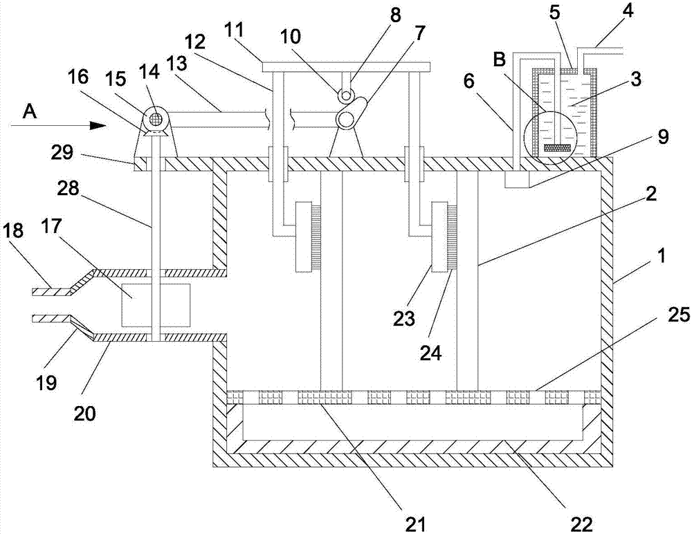
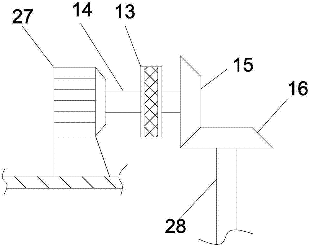
[0020] see Figure 1-4 , a boiler flue gas dust removal and purification device, including a dust removal chamber 1, a speed-increasing tube 20 extending horizontally to the left on the left side wall of the dust-removing chamber 1, and a concentric reducer 19 installed at the left end of the speed-up tube 20, The diameter of the left end of the concentric reducer 19 is smaller than the diameter of the right end, and the left end of the concentric reducer 19 is equipped with an air inlet pipe 18; the left side of the dust removal chamber 1 is fixed with an extension plate 29, and the extension plate 29 is horizontally extended to the left. The drive motor 27 is fixedly installed on the extension plate 29, the drive shaft 14 is fixedly installed on the drive motor 27, the drive shaft 14 is provided with a belt transmission mechanism 13, and the drive shaft...


PUM


Abstract

The invention discloses a boiler fuel gas dedusting purifying device. The boiler fuel gas dedusting purifying device comprises a dedusting chamber; the left side of the dedusting chamber is fixedly provided with an extension board; the extension board is fixedly provided with a driving motor; the driving motor is fixedly provided with a driving shaft; the right end of the driving shaft is fixedly provided with a driving bevel gear; the upper end of a driven shaft is fixedly provided with a driven bevel gear; the driven shaft is fixedly provided with a plurality of blades; the blades are uniformly fixedly arranged on the external surface of the driven shaft along the circumferential direction; two slide bars are arranged on the dedusting chamber; the upper side wall of the dedusting chamber is penetrated by the two slide bars; each of the slide bars is provided with a brushing board; the right side surface of each brushing board is fixedly provided with a hairbrush; the top of the dedusting chamber is provided with a desulphurization tank; one end of a conveyer pipe far from an air pump is provided with an aeration disc; the top of the desulphurization tank is provided with an exhaust pipe. The boiler fuel gas dedusting purifying device is excellent in dedusting filtering effect; flue gas is introduced into the aeration disc for aeration processing, so that sulfides in flue gas are absorbed by a desulfurizer completely, desulphurization effect is excellent; and environment protection emission is realized at last.

Description

technical field [0001] The invention relates to the technical field of environmental protection equipment, in particular to a boiler flue gas dust removal and purification device. Background technique [0002] The boiler is a kind of energy conversion equipment. The energy input to the boiler includes chemical energy and electric energy in the fuel. The boiler outputs steam, high-temperature water or organic heat carrier with a certain amount of heat energy. The original meaning of the pot refers to the water container heated on the fire. Furnace refers to the place where fuel is burned. The boiler includes two parts: the boiler and the furnace. The hot water or steam generated in the boiler can directly provide the required heat energy for industrial production and people's life, and can also be converted into mechanical energy through a steam power device, or regenerated. The boiler that converts mechanical energy into electrical energy through a generator and provides hot...

Claims


Application Information

Patent Timeline
Patent Type & Authority Applications(China)
IPC IPC(8): B01D53/74B01D53/48B01D46/12B01D46/00
CPCB01D46/12B01D53/48B01D53/74B01D2267/30B01D2258/0283B01D46/62B01D46/681
Inventor 张炳强
Owner 张炳强
Why Eureka
Try Eureka