Gas insulation protection jacking electrolytic machining cathode system and machining method
A gas-insulated, cathode technology, applied in the direction of processing electrodes, electric processing equipment, electrochemical processing equipment, etc., can solve problems such as stray corrosion, reduce impact and improve processing quality
- Summary
- Abstract
- Description
- Claims
- Application Information
AI Technical Summary
Problems solved by technology
Method used
Image

Examples
Embodiment Construction
[0015] The specific implementation manners of the present invention are described in detail below.
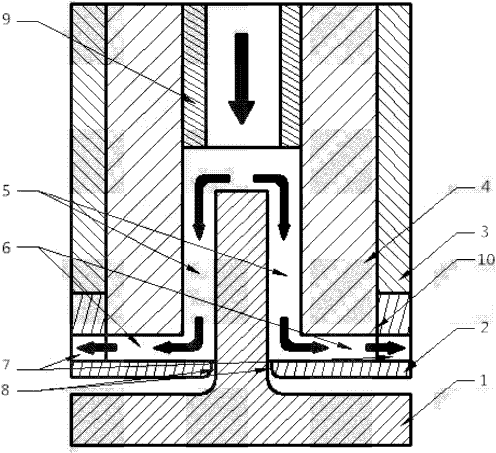
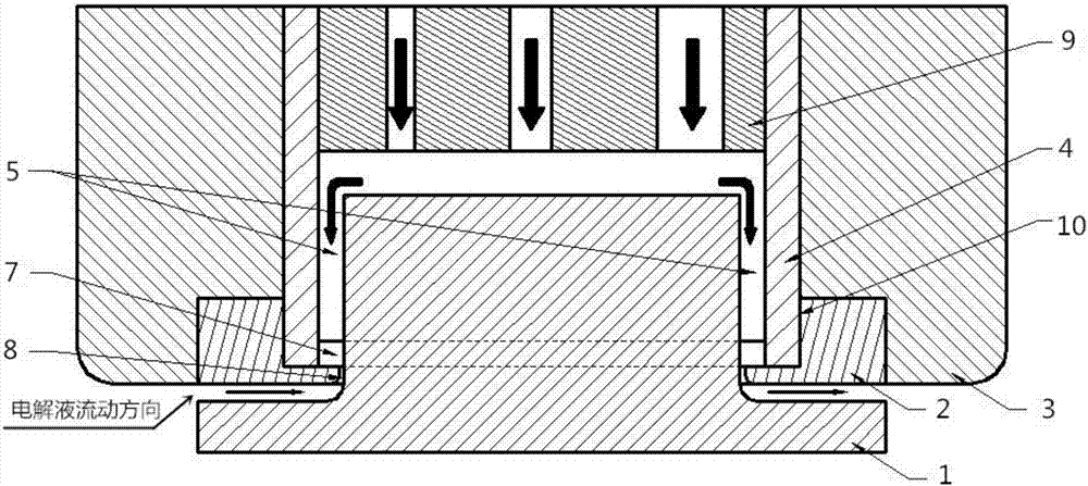
[0016] Implementation of the present invention-"a cathode system and processing method for electrolytic processing of gas-insulated protective casing", the device mainly includes a casing cathode body, a cathode head, a ventilation module, a gas control module and a cathode tailstock.
[0017] The nesting cathode body, cathode head and cathode tailstock are all made of conductive metal materials; the ventilation module and gas control module are made of non-conductive materials; the shape of the cathode edge groove of the cathode head can be designed according to the shape of the processed parts, The width of the ventilation groove on the side of the cathode head and the thickness of the horizontal channel of the ventilation module can be adjusted according to the processing conditions.
[0018] Adopt the process of electrolytic processing workpiece of the present invention to ...
PUM
 Abstract
Description
Claims
Application Information
PatSnap Eureka turns technology decisions into work you can execute. Powered by our Innovation Knowledge Graph, it runs expert workflows across engineering, life sciences, materials and intellectual property. Get your review-ready output in minutes.


