Static-pressure center frame

A center frame and static pressure technology, applied in the direction of grinding workpiece supports, can solve problems such as low efficiency, increased labor costs, and difficulty in ensuring the main force

Pending Publication Date: 2017-08-29
GUNAI HEAVY IND SUZHOU
View PDF10 Cites 0 Cited by
  • Summary
  • Abstract
  • Description
  • Claims
  • Application Information

AI Technical Summary

Problems solved by technology

However, the rotation accuracy of the ordinary center frame itself exceeds 0.01mm, so it is difficult to ensure that the main shaft strength, and the cylindricity of the connecting rod strength are within 0.008mm, and the parallelism with the two tops is within 0.01; so after the fine grinding is completed, manual repair is required. Grinding method to meet the machining accuracy requirements of the crankshaft
[0003] Therefore, the existing large-scale crankshaft machining has the problems of low efficiency, increased labor costs, and difficult to guarantee machining accuracy and quality stability

Method used


Image

  • Static-pressure center frame
  • Static-pressure center frame

Examples


Embodiment Construction

[0023] The following will clearly and completely describe the technical solutions in the embodiments of the present invention with reference to the accompanying drawings in the embodiments of the present invention. Obviously, the described embodiments are only some, not all, embodiments of the present invention. Based on the embodiments of the present invention, all other embodiments obtained by persons of ordinary skill in the art without making creative efforts belong to the protection scope of the present invention.

[0024] The purpose of the present invention is to provide a static pressure center frame to solve the problems in the prior art.

[0025] In order to make the above objects, features and advantages of the present invention more comprehensible, the present invention will be further described in detail below in conjunction with the accompanying drawings and specific embodiments.

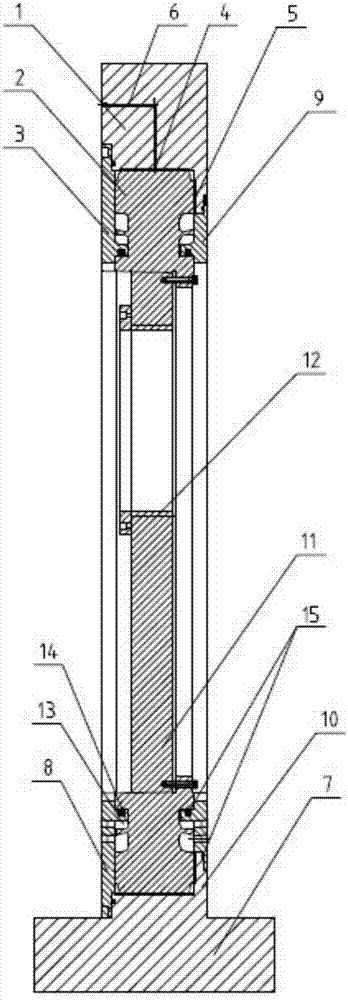
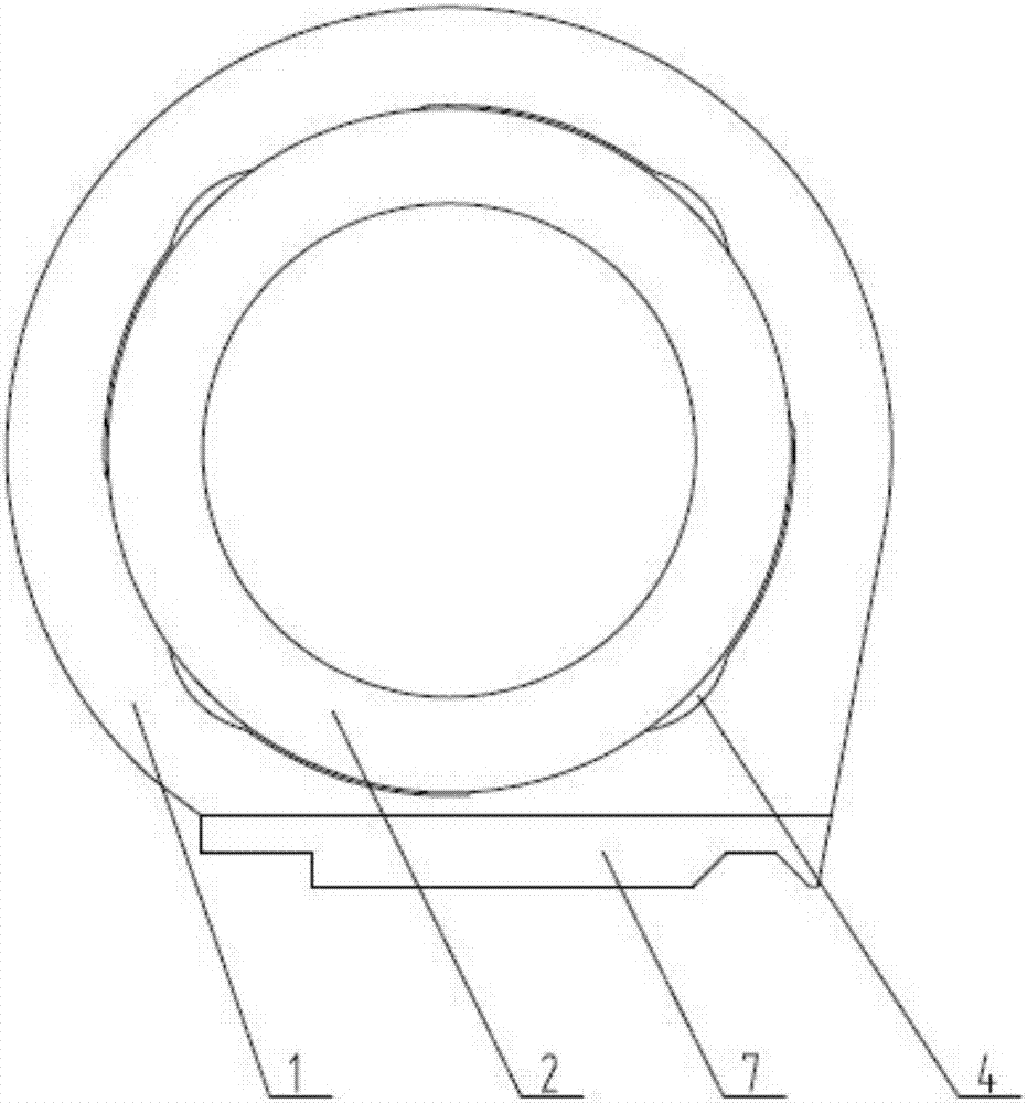
[0026] The invention provides a static pressure center frame, such as Figure 1-2...


PUM


Abstract

The invention discloses a static-pressure center frame which comprises a frame body, a rotor and static-pressure covers. The static-pressure covers are connected with the outer end faces of the two sides of the frame body. The rotor is arranged in a cavity composed of the frame body and the static-pressure covers. An oil film clearance is arranged between the rotor and the inner wall of the frame body, and an oil film clearance is arranged between the inner walls of the static-pressure covers. Radial oil cavities are formed in the positions, opposite to the circumferential outer wall of the rotor, on the circumferential inner wall of the frame body. End face oil cavities are formed in the end faces, in contact with the rotor, of the static-pressure cover and the frame body. The frame body is provided with an oil injection channel communicating with the radial oil cavities and the end face oil cavities. By means of the static-pressure center frame, the rotor can bear external force to conduct high-precision rotation movement, the machining precision of a crankshaft is high, manual coping is not needed, and the machining efficiency is improved.

Description

technical field [0001] The invention relates to the technical field of large-scale crankshaft machining support tooling, in particular to a static pressure center frame. Background technique [0002] The processing quality of the large crankshaft directly determines the quality of the machine operation and is a very critical component. The large crankshaft is about 8 meters long, the blank weight is about 15 tons, and the diameter of the main shaft and connecting rod is within 360. The two ends of the crankshaft are supported by the tops, and the crankshaft is supported by the center frame in the middle. It is necessary to ensure that the main shaft strength of the processed crankshaft and the cylindricity of the connecting rod strength are within 0.008mm, and the parallelism with the two tops is within 0.01. For such a large crankshaft during the processing process Machining efficiency and improving machining accuracy are a very difficult problem to solve. The main way to...

Claims


Application Information

Patent Timeline
IPC IPC(8): B24B41/06
CPCB24B41/065B24B41/067
Inventor 冯学仙曹火光
Owner GUNAI HEAVY IND SUZHOU
Why Eureka
Try Eureka