Butterfly-type cable-stayed bridge system

A cable-stayed bridge and system technology, applied to cable-stayed bridges, bridges, bridge parts, etc., can solve the problems of increased cable force of the main span cable-stayed cables, large stress amplitude of end anchor cables, and increased displacement of the tower top, etc., to achieve The effect of reducing the amount of material, reducing the force, and reducing the deflection deformation

Active Publication Date: 2017-08-29
TONGJI UNIV
View PDF7 Cites 6 Cited by
  • Summary
  • Abstract
  • Description
  • Claims
  • Application Information

AI Technical Summary

Problems solved by technology

When the main span acts on live loads such as vehicles, the main girder deflects downward, resulting in an increase in the cable force of the main span stay cables, and the tower column tends to bend toward the main span, resulting in increased displacement at the top of the tower and a significant increase in the bending moment at the bottom of the tower , so the material consumption in the design of the bridge tower is large, and the economy is not high
Designers often reduce the displacement of the bridge tower and the deflection of the main span by setting the end anchor cables. Therefore, in this case, the design stiffness of the end anchor cables is much larger than that of other stay cables in the span, so that the cable force in the end anchor cables increases significantly. , under the cyclical reciprocation of the live load, the stress amplitude of the end anchor cable is relatively large, which is prone to fatigue problems

Method used


Image

  • Butterfly-type cable-stayed bridge system
  • Butterfly-type cable-stayed bridge system

Examples


Embodiment

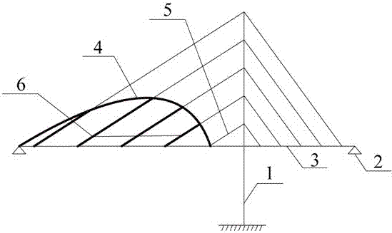
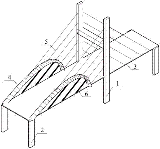
[0021] Embodiment 1: Taking a single-tower cable-stayed bridge as an embodiment, figure 1 It is a schematic diagram (elevation view) of the main structure of the bridge of the present invention, and the cooperation system includes a bridge tower 1, side piers 2, main girder 3, asymmetric curved arch 4, stay cables 5 and inclined suspenders 6.

[0022] The stay cables 5 and the inclined suspenders 6 distributed along the longitudinal direction play the role of elastic support for the main girder 3 . Outside the area of ​​the asymmetric curved arch 4, the two ends of the stay cables 5 are respectively anchored on the bridge tower 1 and the main girder 3; while in the area of ​​the asymmetric curved arch 4, the oblique suspenders 6 are obliquely anchored to the asymmetric curved arch 4 On the arch rib, the oblique suspension rod 6 and the stay cable 5 are anchored at the same point on the arch rib of the asymmetric curved arch 4, and are located on the same straight line, and the...


PUM


Abstract

The invention discloses a butterfly-type cable-stayed bridge system. The system comprises bridge towers, main girders, abutment piers, stayed cables and asymmetric curved arches. The asymmetric curved arches are arranged in a main span, and in the area, the two ends of each stayed cable are connected with the corresponding bridge tower and the corresponding asymmetric curved arch respectively. Inclined suspenders located on the same straight lines of the stayed cables are arranged at anchorage points on arch ribs, and the inclined suspenders are connected with the main girders. Meanwhile, the tension of the inclined suspenders is larger than the cable force of the stayed cables, so that the arch ribs are compressed, and at the moment, loads are born by the stayed cables and an arch-girder system together. The asymmetric curved arches have the stiffening effects on the stayed cables in the areas of the asymmetric curved arches, the main girders, the asymmetric curved arches and the inclined suspenders in the arches form a spatial framework structure together, and the space stiffness of the cable-stayed bridge main span is improved so as to be beneficial to the effect of resisting the wind loads; meanwhile, the downward deflection deformation of the main girders is reduced, the deformation of the stayed cables is reduced, so that the cable force of the main span is reduced, and the stress state of the bridge towers is improved.

Description

technical field [0001] The invention belongs to the field of bridge engineering, in particular to a butterfly cable-stayed bridge system. Background technique [0002] With the continuous development of highway and railway construction in our country, the construction of long-span bridges has developed rapidly, and cable-stayed bridges have been rapidly promoted in our country because of their unique shape and superior spanning ability. The cable-stayed bridges currently built have larger main spans due to navigation and other requirements, so compared with side spans, the stiffness is lower. When the main span acts on live loads such as vehicles, the main girder deflects downward, resulting in an increase in the cable force of the main span stay cables, and the tower column tends to bend toward the main span, resulting in increased displacement at the top of the tower and a significant increase in the bending moment at the bottom of the tower , so the material consumption ...

Claims


Application Information

Patent Timeline
IPC IPC(8): E01D11/04E01D19/00E01D19/16E01D19/14
Inventor 喻隽雅袁万城党新志郭军军李涵冯睿为
Owner TONGJI UNIV
Why Eureka
Try Eureka