

Shield structure cutter head mud cake cutting device and cutting method
A technology of shield cutter head and cutting device, which is used in earth-moving drilling, mining equipment, tunnels, etc., can solve the problems of central scouring device layout and pressure limitation, slow shield tunneling, limited scouring area, etc., and achieves good practicability , The effect of reducing operation risks and completely removing
- Summary
- Abstract
- Description
- Claims
- Application Information
AI Technical Summary
Problems solved by technology
Method used
Image

Examples
Embodiment 1
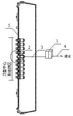
[0039] Embodiment 1: as Image 6 As shown, the nozzle group 2-2 is installed inside the spin-type nozzle 2-1, and the nozzle group 2-2 includes at least 3 nozzles, and the orthographic projection of the nozzles on the self-selecting nozzle 2-1 is The axis of the main shaft 2-3 is the center line and is symmetrically distributed in the spin nozzle 2-1.
[0040] As preferably, the nozzle group includes two cylindrical nozzles and a fan nozzle, a guide tube is installed in the cylindrical nozzle, and a one-way valve is installed at the outlet of the cylindrical nozzle and the fan nozzle to prevent jacking. Damaged and clogged when soiled.
[0041] There is an included angle between the installation direction of the guide tube 2-16 and the direction of the water outlet of the main shaft 2-3, which can drive the spin-type nozzle 2-1 to rotate under the impact of the water flow to perform mud cake cutting and cleaning work. There is an included angle between the installation direc...
Embodiment 2
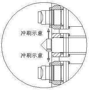
[0042] Embodiment 2: The main shaft 2-3 is equipped with an impeller 2-7, and the impeller 2-7 is located in the water flow channel II. The role of the impeller in changing the water flow path is similar to that of a reflector. After high-pressure water is sprayed on the impeller, the water flow path can be changed.
Embodiment 3
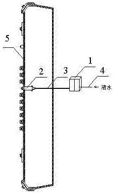
[0043]Embodiment 3: The front end of the main shaft 2-3 is connected to the spin nozzle 2-1, the rear end of the main shaft 2-3 is installed on the main shaft mounting seat 2-4, and the front end of the main shaft mounting seat 2-4 A gland 2-5 is installed, and a cover 2-5 is installed behind the main shaft mounting seat 2-4, and the gland 2-5 is set on the main shaft 2-3, and the gland 2-5 is close to the main shaft A rotary pressure seal 2-6 is installed on one side of the 2-3.
[0044] The gland 2-5 is located in front of the spindle mounting seat 2-4, and is used to isolate the internal structure of the spindle mounting seat 2-4 from the external working space; the side of the gland 2-5 adjacent to the spindle 2-3 has a rotary pressure seal 2-6, which can prevent mud from entering the bearing under the working pressure of 6 bar. The cover 2-10 is located behind the main shaft mounting seat 2-4, and is used to close the water flow cavity at the front end of the cutter barre...
PUM
 Abstract
Description
Claims
Application Information