Check patentability & draft patents in minutes with Patsnap Eureka AI!

Direct-driving magnetic-coupling type harmonic motor

A magnetic coupling and harmonic motor technology, applied in the direction of motors, magnetic circuits, electromechanical devices, etc., can solve the problems of difficult maintenance of the motor-gear transmission system, large motor volume, low output efficiency, etc., to achieve difficult maintenance and high application value, the effect of high power density

Pending Publication Date: 2017-08-29
HARBIN UNIV OF SCI & TECH
View PDF4 Cites 5 Cited by
  • Summary
  • Abstract
  • Description
  • Claims
  • Application Information

AI Technical Summary

Problems solved by technology

[0003] The present invention aims to solve the problems of difficult maintenance, low output efficiency, large vibratio

Method used


Image

  • Direct-driving magnetic-coupling type harmonic motor
  • Direct-driving magnetic-coupling type harmonic motor
  • Direct-driving magnetic-coupling type harmonic motor

Examples


specific Embodiment approach 1

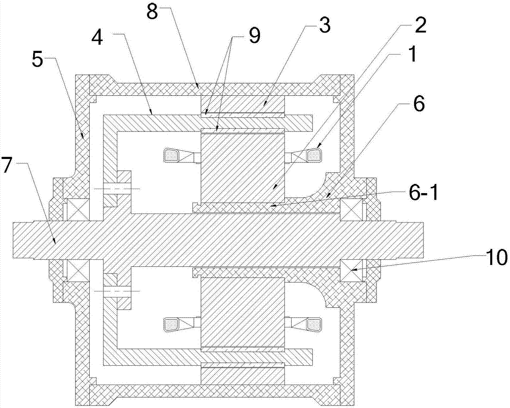
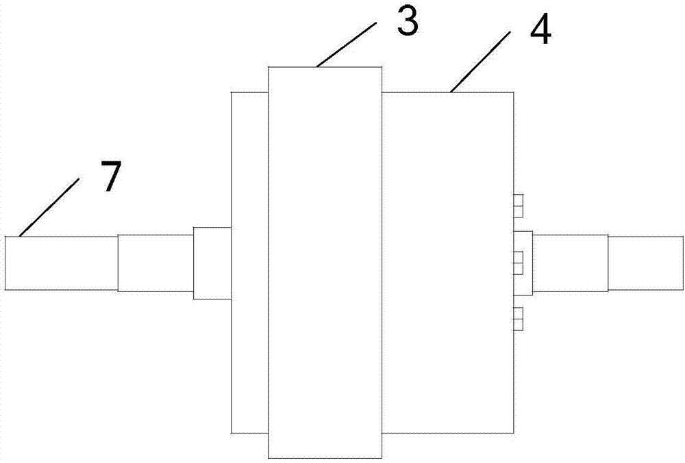
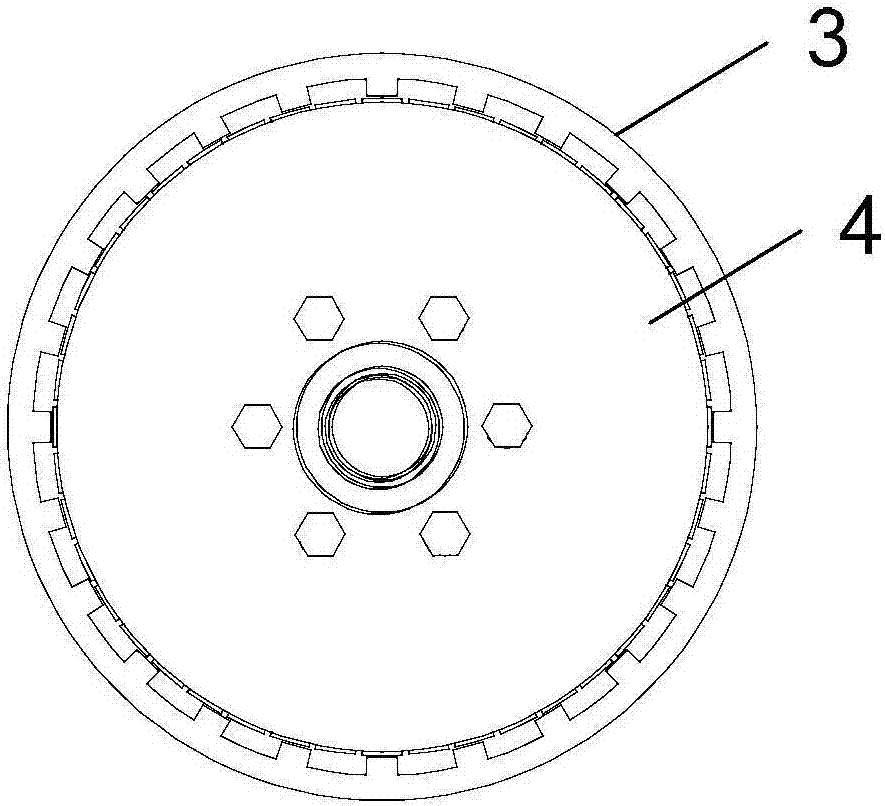
[0035] Specific implementation mode one: see Figure 1 to Figure 19 Describe this embodiment, the direct-drive magnetic coupling type harmonic motor described in this embodiment includes armature winding 1, inner stator 2, outer stator 3, cup-shaped rotor 4, left end cover 5, right end cover 6, rotor Output shaft 7, casing 8 and magnetic steel 9;

[0036] In the radial direction of the rotor output shaft 7, the inner stator 2, the cup-shaped rotor 4, the outer stator 3 and the casing 8 are sheathed in sequence from the inside to the outside. gap;

[0037] The left end cover 5 and the right end cover 6 are respectively covered on the left and right end surfaces of the casing 8, and both are rotationally connected with the rotor output shaft 7 through the bearing 10;

[0038] The cup opening of the cup-shaped rotor 4 faces the right end cover 6, and the cup bottom of the cup-shaped rotor 4 is fixedly connected with the rotor output shaft 7;

[0039] The inner and outer walls ...

specific Embodiment approach 2

[0046] Specific implementation mode two: see Figure 1 to Figure 19Describe this embodiment, the difference between this embodiment and the direct-drive magnetic coupling harmonic motor described in Embodiment 1 is that the magnetic steel 9 on the inner and outer walls of the cup-shaped rotor 4 is respectively connected with the inner stator 2 is set opposite to the outer stator 3, and the axial length of the magnetic steel 9 is greater than or equal to the axial lengths of the inner stator 2 and the outer stator 3.

specific Embodiment approach 3

[0047] Specific implementation mode three: see Figure 1 to Figure 19 This embodiment is described. The difference between this embodiment and the direct-drive magnetic coupling harmonic motor described in Embodiment 1 is that the teeth on the outer stator 3 are arranged opposite to the tooth slots of the inner stator 2 .


PUM


Abstract

A direct-driving magnetic-coupling type harmonic motor relates to the field of direct-driving motor, and solves the problems of difficulty in maintenance, low output efficiency and big vibration noise of the prior motor-gear drive system of the electric automobile, and the huge volume of the conventional direct-driving type motor. An inner stator, a cup-shaped rotor, an outer stator and a shell are orderly sleeved from outside to inside on a radial direction of a rotor output shaft; an air gap is arranged between the cup-shaped rotor and the inner stator, and between the cup-shaped rotor and the outer stator; a left end cover and a right end cover separately cover on the left and right end faces of the shell; the opening of the cup-shaped rotor faces towards the right end cover; the bottom of the cup-shaped rotor is fixedly connected with the rotor output shaft; magnetic steel grooves are set on the inner and outer side walls along the axial direction; magnetic steels are embedded in the magnetic steel grooves; the number of magnetic pole pairs of a armature winding is Ps; the teeth number of each of the inner stator and the outer stator is Ns; the number of magnetic pole pairs on the wall surface of the cup-shaped rotor is Pr; and, Ns=Ps+Pr. The harmonic motor provided by the invention is mainly applied to the direct driving fields of electric automobiles, and so on.

Description

technical field [0001] The invention belongs to the field of direct drive motors. Background technique [0002] Since entering the 21st century, energy shortage has become an important problem restricting the development of various countries, and the development of new energy sources, energy saving and consumption reduction have become research hotspots in various countries. Because traditional fuel vehicles will emit exhaust gas, which will not only pollute the environment but also consume a lot of energy, countries have started research on hybrid vehicles and electric vehicles, and my country has invested a lot of manpower and material resources in the research on electric vehicles. to the forefront of the world. The drive motor is the power component of the electric vehicle and is an indispensable part of it. Although there are many types of electric vehicles available, most of them still use the cooperation of the mechanical deceleration system and the motor to complete ...

Claims


Application Information

Patent Timeline
IPC IPC(8): H02K16/04H02K1/27
CPCH02K1/276H02K16/04H02K2213/03Y02T10/64
Inventor 谢颖黑亮声华邦杰张晓明
Owner HARBIN UNIV OF SCI & TECH
Features
  • R&D
  • Intellectual Property
  • Life Sciences
  • Materials
  • Tech Scout
  • Unparalleled Data Quality
  • Higher Quality Content
  • 60% Fewer Hallucinations
Learn More