Vertical rotor magnetic suspension windmill generator

A technology of wind power generator and magnetic levitation, which is applied in the direction of wind power generator components, wind power engine, wind power motor combination, etc. It can solve the problems of unseen surplus space, large consumption of metal materials, high starting speed, etc., and achieve weight reduction and reduction The effect of reducing the component area and wind rotor area

Inactive Publication Date: 2013-11-06
SHENZHEN TYPMAR WIND ENERGY TECH CO LTD
View PDF0 Cites 0 Cited by
  • Summary
  • Abstract
  • Description
  • Claims
  • Application Information

AI Technical Summary

Problems solved by technology

The diameter of the 5KW maglev wind turbine is even as large as 1000mm, which not only consumes a lot of metal materials, but also has the defects of heavy fan and high starting speed
The design of the outer rotor of the maglev wind turbine has more space to place the permanent magnet poles. The outer rotor is exposed to the outside and can be cooled by the natural wind outside the machine base. The centrifugal force of the rotor rotation can make the fixation of the magnetic poles more firm. However, There has not yet been seen a deep-level use of the surplus space of the outer rotor and changing the stator winding method to effectively relieve the constraints of the magnetic poles and the number of coil turns on the power generation of the magnetic levitation wind turbine, which requires high current and high voltage.

Method used


Image

  • Vertical rotor magnetic suspension windmill generator
  • Vertical rotor magnetic suspension windmill generator
  • Vertical rotor magnetic suspension windmill generator

Examples


Embodiment Construction

[0024] The present invention will be described below in combination with specific embodiments and with reference to the accompanying drawings.

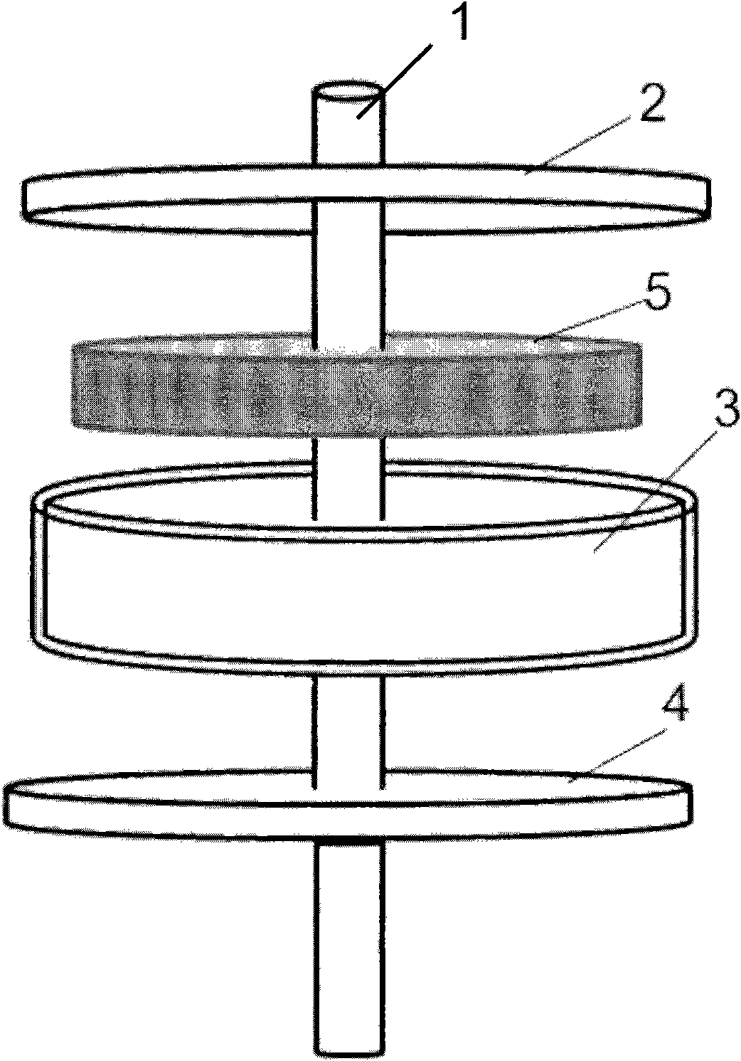
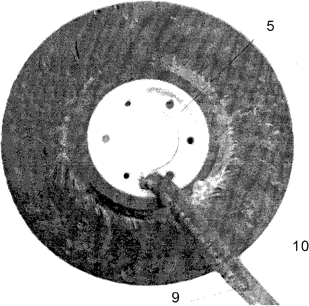
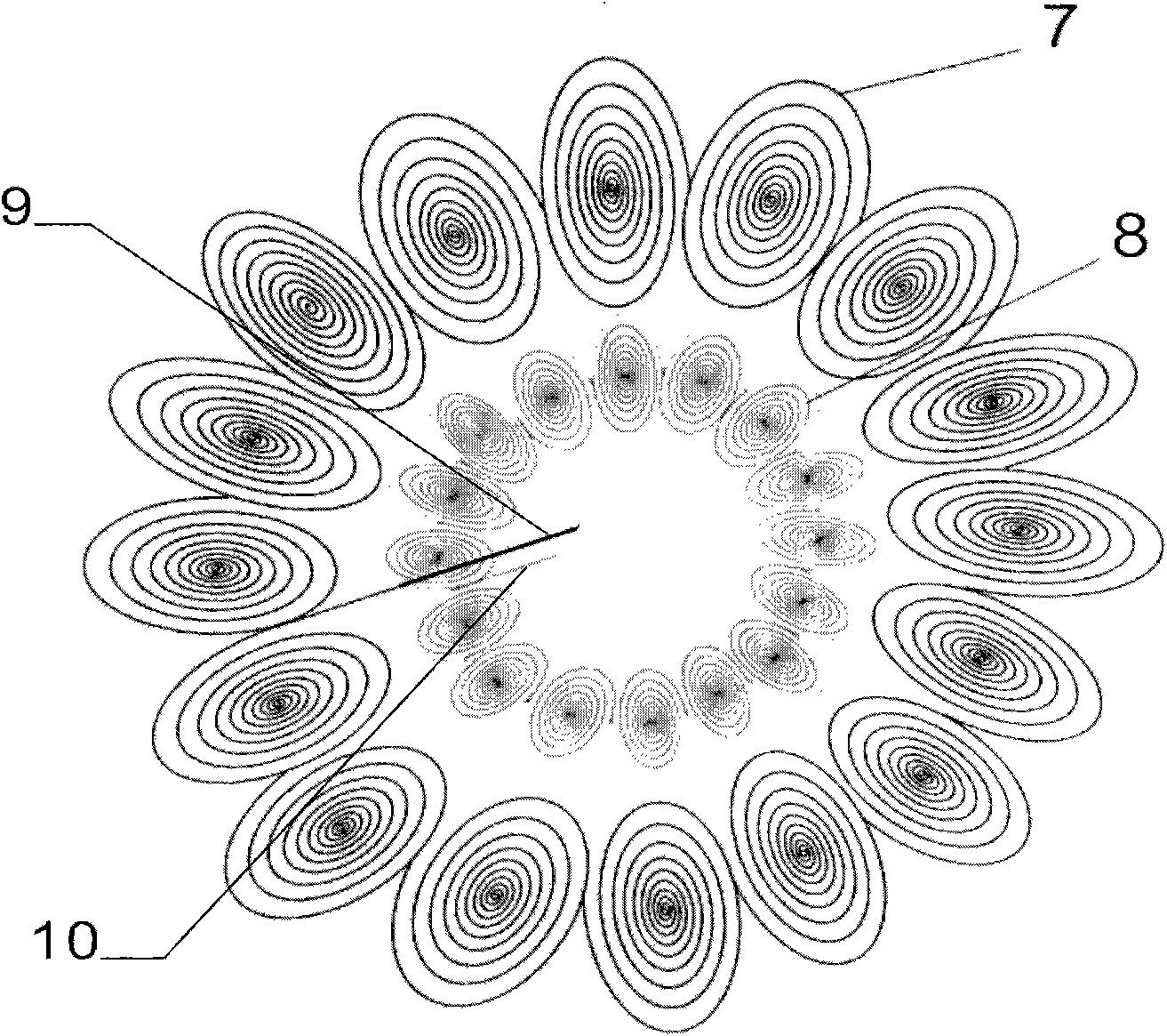
[0025] a kind of like Figure 1~4 The shown direct-drive outer rotor permanent magnet synchronous vertical axis magnetic levitation wind turbine includes a main shaft 1, a disc-shaped casing composed of an upper casing cover 2, a cylindrical casing 3 with a short axial dimension in the middle, and a lower casing cover 4, and a stator. 5 and the outer rotor, the stator 5 is arranged in the disc-shaped housing, the outer rotor is an outer rotor composed of the upper case cover 2 and the lower case cover 4 and is connected with the main shaft 1 through interference fit, the upper case cover 2 and the lower case cover 4 There are outer trapezoidal pole grooves on the inner side of the near outer circumference of the 16 fan-shaped areas divided equally according to the set number of magnetic poles on the side, and a magnetic pole 6 formed ...


PUM


Abstract

The invention discloses a vertical shaft magnetic suspension windmill generator. The windmill generator comprises a main shaft, a disk-shaped shell, a stator and an outer rotor, wherein the outer rotor is composed of an upper shell cover and a lower shell cover and provided with two magnetic poles corresponding to the two windings of the stator; the parts near the outer circumferences of the insides of fan sections, which are equally divided according to the set number of magnetic poles, on the inner side surfaces of the upper shell cover and the lower shell cover are separately provided with an outer trapezoidal polar trough, a high-magnetic-energy permanent magnetic material of which polarities are arranged alternately is embedded in the outer polar troughs to form a magnetic pole; and the parts near the centers of the insides of the fan sections are separately provided with an inner trapezoidal polar trough, and the high-magnetic-energy permanent magnetic material of which polarities are arranged alternately is embedded in inner trapezoidal polar troughs to form another magnetic pole. The two windings of which wires are distributed from outside to inside or from inside to outside are embedded in the flat surface of the stator; one winding is a large winding arranged on the inside of the external circumference of the stator, the other winding is a small winding arranged on the inside of the large winding. The windmill generator is characterized by small electric motor, long winding and large number of poles and can effectively overcome the constraints of the magnetic pole and the number of coils to meet the generating demands of the magnetic suspension windmill generator, namely large current and high voltage.

Description

technical field [0001] The invention relates to a generator, in particular to a vertical axis magnetic levitation wind power generator adopting a double-winding internal rotation method. Background technique [0002] The power generation of the vertical axis maglev wind turbine is restricted by the number of magnetic poles and coil turns. The need for large current and high voltage requires an increase in the number of magnetic poles and a corresponding increase in the number of coil turns. The coreless wind turbines introduced in recent years are getting bigger and bigger in order to increase the current and voltage. The diameter of the 5KW maglev wind turbine is even as large as 1000mm, which not only consumes a lot of metal materials, but also has the defects of heavy fan and high starting speed. The design of the outer rotor of the maglev wind turbine has more space to place the permanent magnet poles. The outer rotor is exposed to the outside and can be cooled by the ...

Claims


Application Information

Patent Timeline
Patent Type & Authority Patents(China)
IPC IPC(8): F03D9/00F03D11/00H02K3/04H02K15/04
CPCY02E10/725Y02E10/722Y02E10/72
Inventor 林文奇
Owner SHENZHEN TYPMAR WIND ENERGY TECH CO LTD
Why Eureka
Try Eureka