Alternating-current generator and stator thereof

A technology for alternators and stators, which is applied to the static parts of the magnetic circuit, and the shape/style/structure of the magnetic circuit. efficiency, cost savings, and copper wire savings

Active Publication Date: 2014-05-07
JINZHOU HALLA ELECTRICAL EQUIP
View PDF3 Cites 0 Cited by
  • Summary
  • Abstract
  • Description
  • Claims
  • Application Information

AI Technical Summary

Problems solved by technology

[0002] The stator winding of a traditional alternator is wound with a complete copper wire, which has been bent many times. In the case of a high slot full rate of the stator, the winding cannot be assembled
In addition, the copper wire outside the stator core of the generator is less involved in the cutting of the magnetic induction line, and the utilization efficiency of the copper wire is very low, resulting in a waste of copper wire and increasing the cost
In addition, as attached Figure 5 As shown, the wiring method of the traditional stator winding is equivalent to connecting in series and then in parallel, that is, the resistance of each phase is equivalent to multiple resistors R' in series, the total resistance of the system is equivalent to the total resistance of each phase in parallel, and the resistance generated by the copper wire is large , large heat loss

Method used


Image

  • Alternating-current generator and stator thereof
  • Alternating-current generator and stator thereof
  • Alternating-current generator and stator thereof

Examples


Embodiment Construction

[0022] The present invention will be described in detail below with reference to the accompanying drawings and in combination with embodiments.

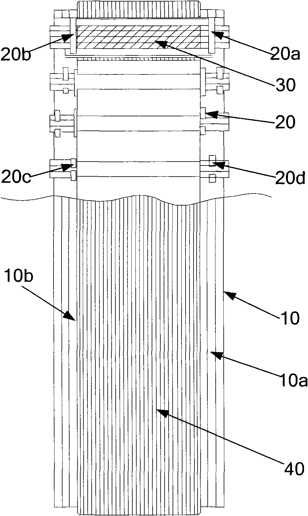
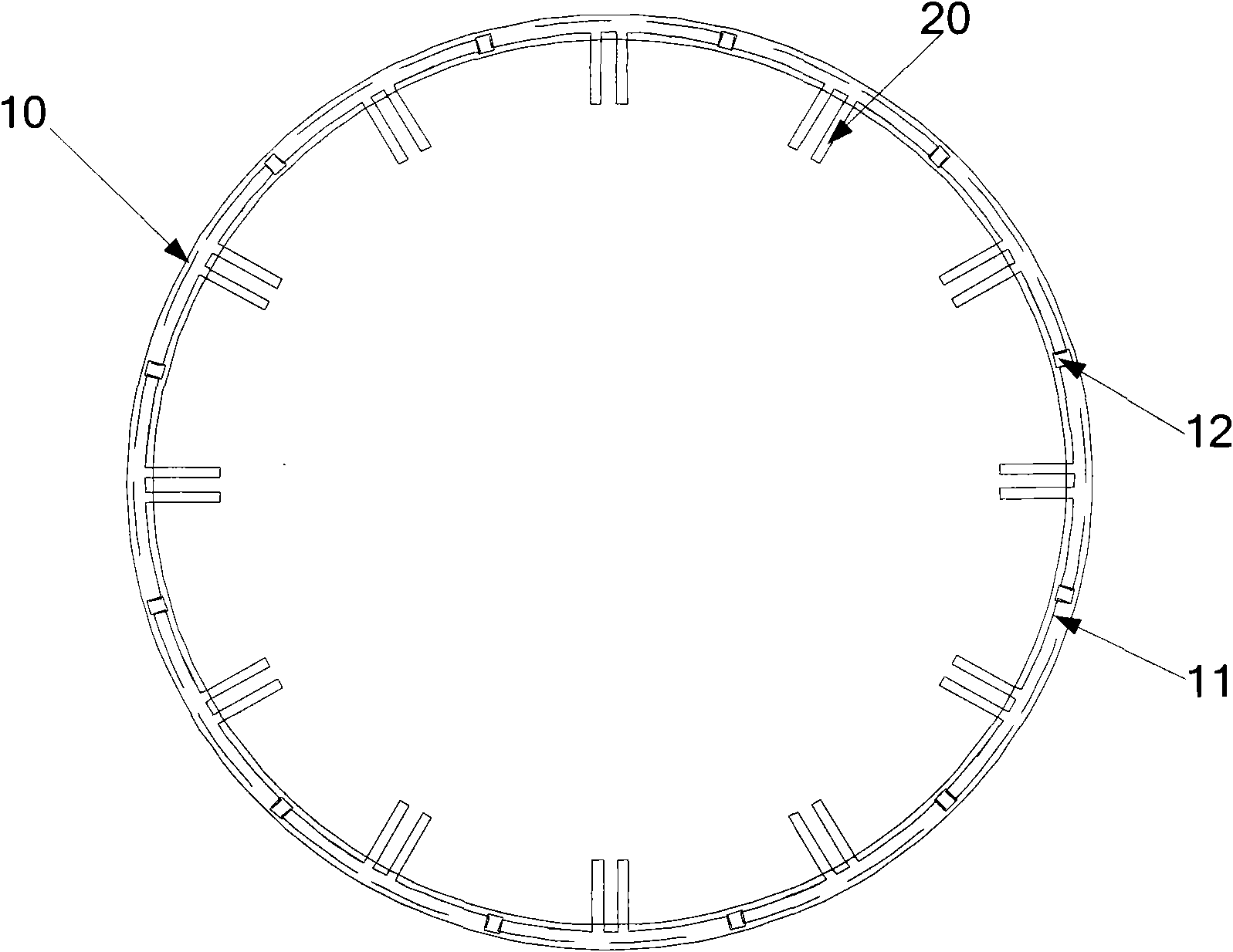
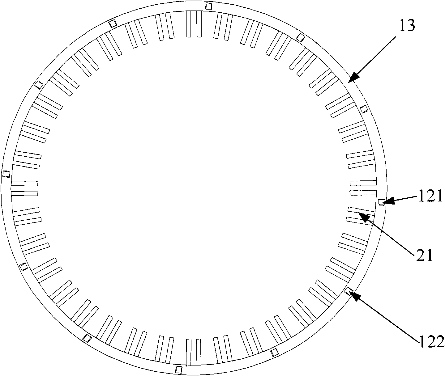
[0023] Attached below Figures 1 to 4 as well as Figure 6 A first embodiment of the alternator stator according to the present invention will be described in detail.

[0024] Such as figure 1 and Figure 4 As shown, an alternator stator includes a stator core 40, and the alternator stator also includes: a ring circuit board 10, a plurality of ring circuit boards 10 are symmetrically distributed on both sides of the stator core 40; a plurality of clamps 20, The wire clip 20 is located on the ring circuit board 10 and is electrically connected with the ring circuit board 10; a plurality of magnetic induction cutting parts 30, the two ends of each magnetic induction cutting part 30 are respectively located in the wire clip 20, and are connected with the card The clip 20 is electrically connected. Wherein, the magnetic induction l...


PUM


Abstract

The invention provides an alternating-current generator and a stator thereof. The alternating-current generator stator provided by the invention comprises a stator iron core and also comprises multiple annular circuit boards, multiple line-clamping chips, multiple magnetic induction line cutting components, wherein the multiple annular circuit boards are symmetrically distributed at the two sides of the stator iron core; the multiple line-clamping chips are located on the annular circuit boards and electrically connected with the annular circuit boards; the two ends of each magnetic induction line cutting component are positioned in each line-clamping chip and electrically connected with each line-clamping chip; and the magnetic induction line cutting components are arranged on the inner surface of the alternating-current generator stator through the line-clamping chips, and the magnetic induction line cutting components which are in the same phase are successively connected through the annular circuit boards. According to the alternating-current generator stator provided by the invention, multiple segments of magnetic induction line cutting components and the annular circuit boards are used as three-phase windings to cut magnetic induction lines without bending parts among the magnetic induction line cutting components so that the tank-full rate of the inserting coil of the stator is improved.

Description

technical field [0001] The invention relates to the field of a vehicle alternator, and more specifically relates to an alternator and a stator thereof. Background technique [0002] The stator winding of the traditional alternator is wound by a complete copper wire, which has been bent many times, and the winding cannot be assembled in the case of a high slot fullness of the stator. In addition, the copper wire outside the stator core of the generator is less involved in the cutting of the magnetic induction line, and the utilization efficiency of the copper wire is very low, which causes waste of copper wire and increases the cost. In addition, as attached Figure 5 As shown, the wiring method of the traditional stator winding is equivalent to connecting in series and then in parallel, that is, the resistance of each phase is equivalent to multiple resistors R' in series, the total resistance of the system is equivalent to the total resistance of each phase in parallel, and...

Claims


Application Information

Patent Timeline
Patent Type & Authority Patents(China)
IPC IPC(8): H02K1/16H02K1/18
Inventor 唐磊陈蕴超王鑫牟晓松司秉树刘爽
Owner JINZHOU HALLA ELECTRICAL EQUIP
Why Eureka
Try Eureka