Chained single bridge self-coupling boost topology

A single-bridge, chain-type technology, used in instruments, electrical variables, output power conversion devices, etc., can solve the problems of low reliability, low output power, large volume, etc., to reduce volume and materials, save The effect of copper wire

Inactive Publication Date: 2016-04-20
AEROSPACE CHANGFENG CHAOYANG POWER SUPPLY
View PDF4 Cites 0 Cited by
  • Summary
  • Abstract
  • Description
  • Claims
  • Application Information

AI Technical Summary

Problems solved by technology

[0007] The technical problem to be solved by the present invention is to overcome the defects of low output power, large volume, low efficiency and low reliability of the forward step-up DC converter in the prior art, and provide a chain-type single-bridge self-coupling booster Voltage topology conversion circuit, which realizes the positive step-up power supply under the same power and electrical parameters requirements, the volume is reduced by 50%, the output power is doubled, the efficiency is increased by 10%, and the highest efficiency can reach 96%.

Method used


Image

  • Chained single bridge self-coupling boost topology
  • Chained single bridge self-coupling boost topology
  • Chained single bridge self-coupling boost topology

Examples


Embodiment Construction

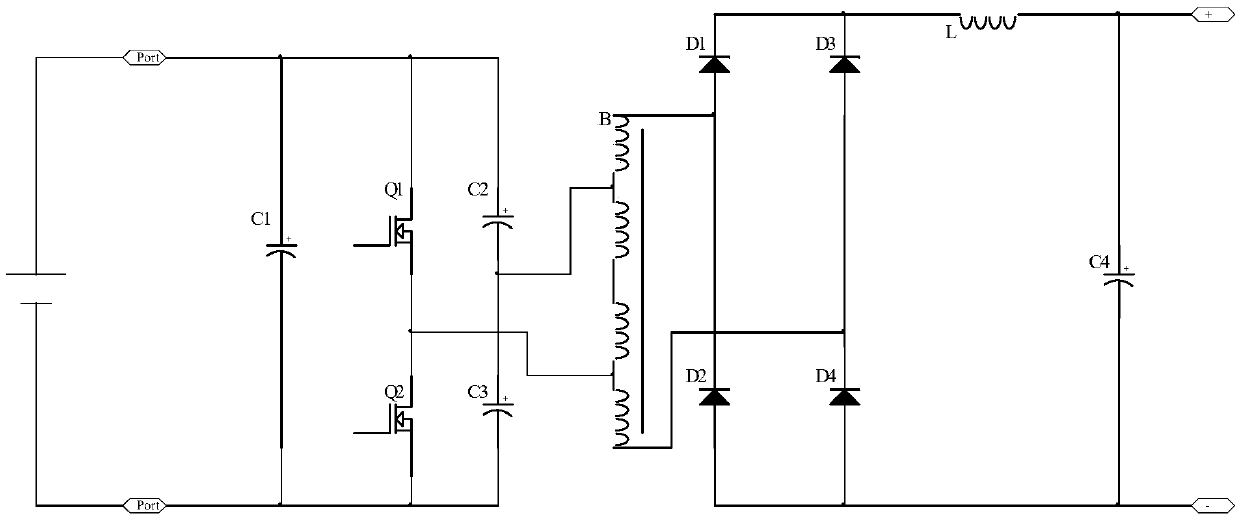
[0025] Such as image 3 As shown, the present invention provides a chain-type single-bridge self-coupling boost topology conversion circuit, the circuit consists of two power switch MOS transistors Q1, Q2, two capacitors C2, C3, a non-coupling high-frequency chain forward boost Voltage transformer B, a secondary full-bridge rectifier circuit, an output filter inductor L, and an output filter capacitor C4. Capacitors C2, C3 and MOS tubes Q1, Q2 form a half bridge. When C2=C3, when a switch tube is turned on, the voltage of transformer B is only half of the power supply voltage.

[0026] The working process of the present invention is as image 3 Shown:

[0027] 1. When Q1 is turned on and Q2 is turned off, the voltage applied to both ends of the transformer is half of the bus voltage, and the energy is transferred from the primary side to the secondary side. =K*D*Vin, (K: Turns ratio; D: Duty ratio; Vin: Input DC voltage) Since the turns ratio K>1, the output voltage is hig...


PUM


Abstract

The invention relates to a chained single bridge self-coupling boost topology circuit, comprising a power switch MOS Q1, a power switch MOS Q2, two capacitors C2 and C3, a no-coupling high frequency chain positive boost transformer B, a secondary full bridge rectification circuit D1, D2, D3, and D4, an output filtering inductor L, and an output filtering capacitor C4. The capacitors C2 and C3 and the MOS Q1 and Q2 form a half bridge. When C2=C3, and one switch MOS is conducted, the voltage of the transformer B is only half of the voltage of a power supply. The technology reduces the size of a positive boost power supply by 75%, doubles the output power, increases the efficiency by 10%, and realizes the efficiency as high as 96%.

Description

technical field [0001] The invention relates to a chain-type single-bridge self-coupling boost topology circuit. Background technique [0002] At present, there are BOOST booster circuits and flyback-based booster circuit topologies commonly used in forward boost switching power supply circuits at home and abroad. [0003] The main circuit diagram of the BOOST boost circuit is as follows: figure 1 As shown, its working principle is: the input power stores the energy in the energy storage inductance L through the on and off of the power switch tube Q and superimposes it with the input voltage, and then transfers it to the output capacitor C through the isolation diode D to complete the boosting process. [0004] The main circuit diagram of the boost topology based on flyback is as follows: figure 2 As shown, when the switch tube Q is turned on, the primary coil of the transformer B stores energy, and when the switch tube is turned off, the primary energy storage is coupled...

Claims


Application Information

Patent Timeline
Patent Type & Authority Applications(China)
IPC IPC(8): H02M3/335
CPCH02M3/3353
Inventor 刘建华高海燕谢振利
Owner AEROSPACE CHANGFENG CHAOYANG POWER SUPPLY
Why Eureka
Try Eureka