
Door latch system

一种门闩、锁定构件的技术,应用在门闩系统领域,能够解决受损、门闩系统结构复杂、高昂维修费用等问题,达到降低制造成本、减少数量、形状紧凑的效果

Active Publication Date: 2017-08-29
WOOBO TECH CO LTD
View PDF5 Cites 13 Cited by
  • Summary
  • Abstract
  • Description
  • Claims
  • Application Information

AI Technical Summary

Problems solved by technology

[0003] However, such a latch system of the prior art has a problem that when the door handle is pulled with the door locked, unnecessary force is applied to various components such as the latch connected to the door handle, and therefore, the latch system The various components of the can be easily damaged, thus, there is a problem of high repair costs
[0004] Furthermore, the structure of such latch systems of the prior art is complex

Method used


Image

  • Door latch system
  • Door latch system
  • Door latch system

Examples


Embodiment approach 1

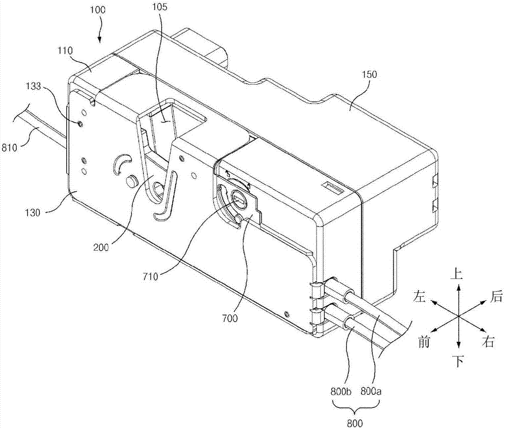
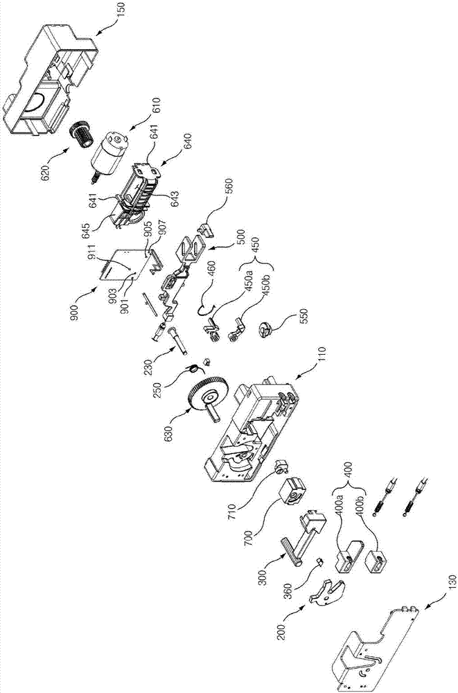
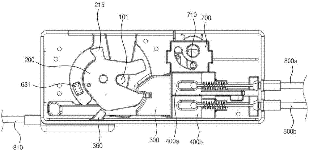
[0179] like Figure 1 to Figure 33 As shown, the door latch system according to the first example embodiment of the present invention includes: a housing 100; a latch 200 installed in the housing 100 in a pivotable and rotatable manner; the main locking member 300 to lock the latch 200; the sub-locking member 400 slidably installed in the casing 100 and arranged on one side of the main locking member 300; and the main locking member 300 and the sub-locking member 400 can be Simultaneously sliding or only sliding of the sub-locking member 400 connection means.

[0180] like Figure 1 to Figure 13 As shown, the casing 100 includes: a first casing 110 , a second casing 130 arranged in front of the first casing 110 , and a third casing 150 arranged behind the first casing 110 .

[0181] like figure 1 As shown, in the housing 100 , front means a direction toward the second housing 130 , and rear means a direction toward the third housing 150 . In addition, the left side and the...

Embodiment approach 2

[0471] In describing the latch system according to the second embodiment of the present invention, the same reference numerals will be used for the same or similar elements as those of the latch system according to the first embodiment of the present invention, and detailed description and explanation thereof will be omitted. .

[0472] like Figure 34 to Figure 40 As shown, the door latch system according to the second example embodiment of the present invention further includes: a rotating member 370 for sliding the main locking member 300'

[0473]Since only the body 310' of the main locking member 300' is formed in a different form from the first example embodiment of the present invention, only the body 310' will be described, and descriptions of other identical configurations will be omitted.

[0474] The body 310' constitutes the right part of the main locking member 300'.

[0475] The body 310' includes a first stepped portion 311' and a second stepped portion 3...

Embodiment approach 3

[0520] like Figure 41 to Figure 72 As shown, the door latch system according to the first example embodiment of the present invention is characterized by and includes: a housing 4100; a latch 4200 pivotally and rotatably mounted in the housing 4100; A main locking member 4300 in 4100 to lock the latch 4200; and a drive unit 4600 for pivotally rotating the latch 4200, wherein the drive unit 4600 includes a main gear 4630, wherein an engaging portion of gear teeth is formed 4632 is formed on a part of the circumferential surface of the main gear 4630 , and a non-engaging portion 4643 (no gear teeth) is formed on the remaining portion of the circumferential surface of the main gear 4630 .

[0521] like Figure 41 to Figure 44 As shown, the housing 4100 includes: a first housing 4110 , a second housing 4130 disposed in front of the first housing 4110 , and a third housing 4150 disposed at the rear of the first housing 4110 .

[0522] A striker insertion groove 4105 is formed on...


PUM


Abstract

This invention relates to a door latch system. The door latch system includes: a housing; a latch pivotally and rotatably installed in the housing; a main locking member slidingly installed in the housing for locking the latch; a sub-locking member slidingly installed in the housing and disposed in one side of the main locking member; a hook pivotally and movably installed in any one of the main locking member and the sub-locking member; a stopping threshold formed in the other one (wherein the hook is not installed) of the main locking member and the sub-locking member; and a locking plate slidingly installed in the housing for pivotally moving the hook, wherein the main locking member and the sub-locking member are sliding together when the hook is held by the stopping threshold by the sliding of the locking plate, and only the sub-locking member is sliding when the hook is separated from the stopping threshold by the sliding of the locking plate, so that even if the door lever is being pulled when the door is being locked, the unnecessary force is not transferred to the other components such as a latch, a main locking member, and the like.

Description

technical field [0001] The present invention relates to a door latch system, and more particularly, to a door latch system capable of preventing the bolt, main locking member, etc. The door can be set to a locked state or an unlocked state with a simple structure. Background technique [0002] As suggested in Korean Patent No. 0535053, generally, a door latch system is used to open or close a car door or to lock or unlock a car door. [0003] However, such a latch system of the prior art has a problem that when the door handle is pulled with the door locked, unnecessary force is applied to various components such as the latch connected to the door handle, and therefore, the latch system The various components of the system may be easily damaged, thus, there is a problem of high repair costs. [0004] Furthermore, the construction of such prior art latch systems is complex. [0005] main technical literature [0006] patent documents [0007] Patent Document 1 Korean Pat...

Claims


Application Information

Patent Timeline
Patent Type & Authority Applications(China)
IPC IPC(8): E05B81/24E05B85/00
CPCE05B77/32E05B79/20E05B81/06E05B81/20E05B81/34E05B81/64E05B81/66E05B15/04E05B77/26E05B77/44E05B81/16E05B81/38E05B81/54E05B81/74E05B83/36E05B85/243E05B85/26E05Y2201/72E05Y2400/44E05Y2900/531
Inventor 丁海一
Owner WOOBO TECH CO LTD
Learn More