Concentrating Particles in Microfluidic Devices
A technology of microfluidic devices and microfluidic channels, which can be used in individual particle analysis, measurement devices, fluid controllers, etc., to solve problems such as limitations and low yields
- Summary
- Abstract
- Description
- Claims
- Application Information
AI Technical Summary
Problems solved by technology
Method used
Image
Examples
example 1
[0240] Example 1: Cell-free layer growth and percent siphoning
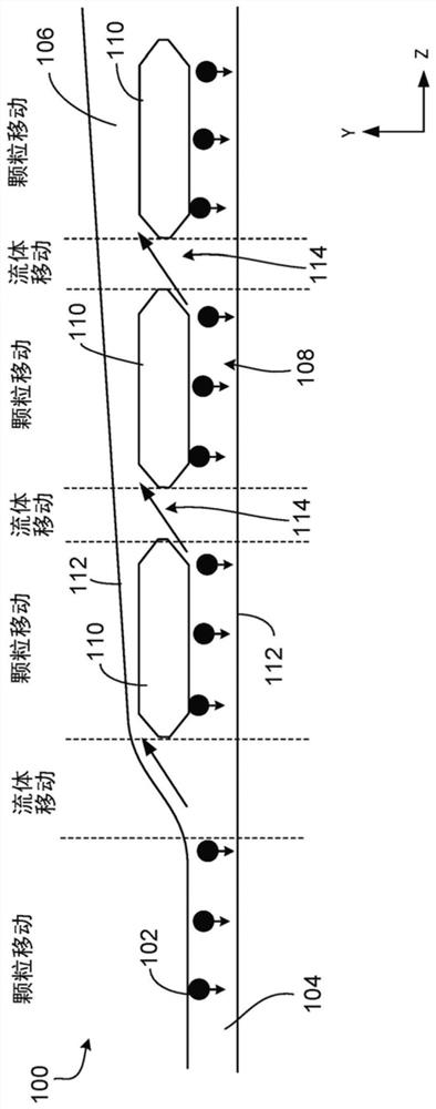
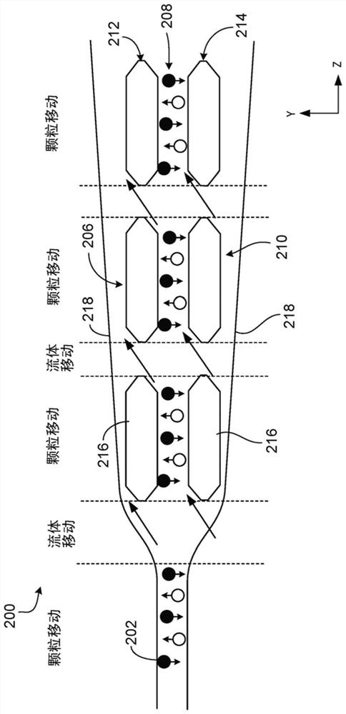
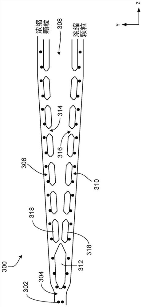
[0241] The combined siphon and inertial focusing design has the advantage of fast acting inertial forces that create a particle-free layer near the walls of the microfluidic channel. This layer of particle-free fluid is then controllably siphoned away, again leaving the particles closer to the wall where the inertial forces are strongest. The process of agglomeration and siphoning can be repeated until the desired volume reduction is obtained. When using microfluidic devices to enhance the concentration of particles within a fluid or to extract a particle-free fluid, important design considerations may include controlling the percentage of fluid that is siphoned relative to the kinetics of the formation of a particle-free layer. In inertial aggregation systems, aggregation behavior is the cumulative result of many parameters including channel geometry as well as flow velocity (see, for example, Di Carlo, D. "I...
example 2
[0248] Example 2: Flow rate dependence
[0249] Another factor that may be considered in microfluidic systems for performing volume reduction and / or increasing particle concentration within a fluid is the flow rate of a fluid sample through the microfluidic device. Therefore, the sensitivity to flow rate was also investigated. The yields of both the 10x and 50x devices were analyzed between input flow rates of 100 μl / min to 1000 μl / min using isolated white blood cells (buffy coat). Yield is calculated on a relative basis between the number of cells in the stream flowing in the aggregation channel and the number of cells in the second fluid flow region, or alternatively, as the total number of cells in the stream flowing in the aggregation channel. Divide the number by the total cells in the combination of aggregation channels and second fluid flow channels. The high throughput of the device, greater than 95%, was maintained between 400 and 600 μl / min, but beyond this range...
example 3
[0252] Example 3: Size Dependency
[0253]The inertial force depends largely on the size of the particles being aggregated. Therefore, the performance of the combined inertial aggregation and siphon device was evaluated for sensitivity to particle size. Specifically, various polystyrene particle sizes (4 μm-10 μm) were run simultaneously through the 10x and 50x setups in order to determine the size range of particles deflected from the aggregation channel to the second fluid flow region where the "particle free" layer is desired. Figure 13 is a plot of the previous experiment and shows that smaller particle sizes have lower relative yields than larger particle sizes (i.e., (total cells in product) / (total cells in product+total cells in waste )), that is, the smaller the particle, the more likely it is that the particle will escape the aggregation channel through the gaps between the island structures. If a relative yield above 90% is desired, the cutoff particle size for ...
PUM
| Property | Measurement | Unit |
|---|---|---|
| diameter | aaaaa | aaaaa |
| molecular weight | aaaaa | aaaaa |
| length | aaaaa | aaaaa |
Abstract
Description
Claims
Application Information
 - R&D Engineer
- R&D Manager
- IP Professional
- Industry Leading Data Capabilities
- Powerful AI technology
- Patent DNA Extraction
Browse by: Latest US Patents, China's latest patents, Technical Efficacy Thesaurus, Application Domain, Technology Topic.
© 2024 PatSnap. All rights reserved.Legal|Privacy policy|Modern Slavery Act Transparency Statement|Sitemap


