
Smoking machine

A smoking machine and smoking technology, which is applied in the field of smoking machines, can solve the problem of difficulty in determining the completion time of smoke exhaust, and achieve the effects of ensuring continuity and improving production efficiency.

Inactive Publication Date: 2017-09-01
福建白水洋生物科技有限公司
View PDF8 Cites 2 Cited by
  • Summary
  • Abstract
  • Description
  • Claims
  • Application Information

AI Technical Summary

Problems solved by technology

[0006] The technical problem to be solved by the present invention is to provide a smoker to solve the problem that the smoke exhausting completion time of the existing smoker is difficult to determine after the smoking process is completed

Method used


Image

  • Smoking machine
  • Smoking machine

Examples


Embodiment 1

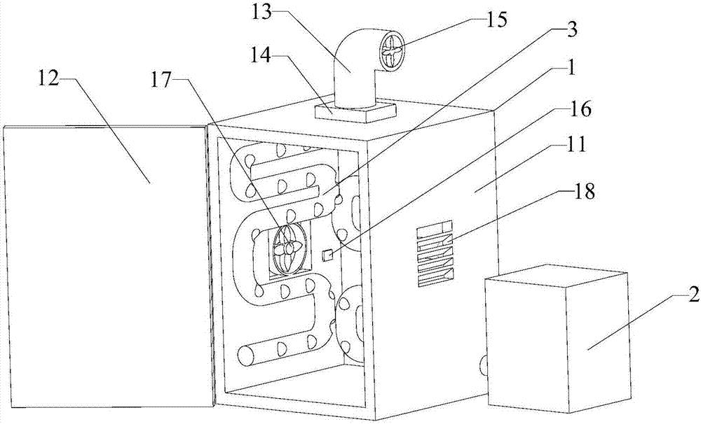
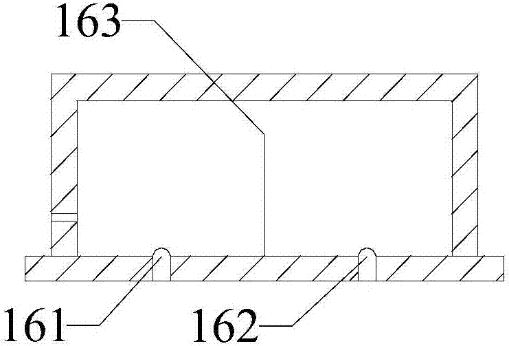
[0053] Please refer to the figure, a smoker includes a smoker 1 and a smoker 2; the smoker 1 is connected to the smoker 2 through a smoker pipe 3; the smoker 1 includes a cabinet body 11, a cabinet Door 12, smoke exhaust pipe 13, smoke exhaust pipe valve 14, exhaust fan 15, control panel, smoke sensor 16 and alarm device; the shape of the cabinet body 11 is rectangular, and the inner wall of the cabinet body 11 is provided with a smoke sensor 16, so The outer wall of the cabinet body 11 is provided with an alarm device, and the smoke sensor 16 is electrically connected to the alarm device; the upper part of the cabinet body 11 is connected to a smoke exhaust pipe 13, and the smoke exhaust pipe 13 is provided with a smoke exhaust pipe valve 14, so The exhaust pipe 13 is provided with an exhaust fan 15, the exhaust pipe valve 14 is electrically connected to the smoke sensor 16, the exhaust fan 15 is electrically connected to the smoke sensor 16, and the outer surface of the cabin...

Embodiment 2

[0055] A fumigator, the inner section of the cabinet of the fumigating pipe 3 is provided with an opening at intervals of 20 cm; other features are the same as in embodiment 1.

Embodiment 3

[0057] A fumigator, wherein an opening is arranged at intervals of 15 cm in the cabinet inner section of the fumigating pipeline 3 ; other features are the same as those in Embodiment 1.

[0058] To sum up, the smoking furnace provided by the present invention is provided with a smoke sensor inside the cabinet and an alarm device electrically connected to the smoke sensor outside the cabinet. When the smoke in the cabinet is emptied, the alarm device will remind workers in time Open the cabinet door to smoke the next batch of food; on the one hand, it ensures the continuity of the smoking process, so that when the smoker needs to process a large amount of food, it can work without interruption and improve production efficiency; on the other hand, it ensures In order to open the cabinet door, the smoke in the cabinet has been evacuated, which will not pollute the closed processing workshop.


PUM


Abstract

The invention relates to a smoking machine. The smoking machine comprises a smoking cabinet and a smoke producing furnace; the smoking cabinet is connected with the smoke producing furnace via a smoking pipeline; the smoking cabinet comprises a cabinet body, a cabinet gate, a smoke exhaust pipe, a smoke exhaust pipe valve, a draft fan, a control panel, a smoke sensor, and an alarm; the smoke sensor is arranged on an inner wall of the cabinet body; the alarm is arranged on an outer wall of the cabinet body; the smoke sensor and the alarm are in electrical connection; an upper part of the cabinet body is connected with the smoke exhaust pipe; the smoke exhaust pipe valve is arranged in the smoke exhaust pipe; the draft fan is arranged in the smoke exhaust pipe; the smoke exhaust pipe valve and the smoke sensor are in electrical connection; the draft fan and the smoke sensor are in electrical connection; and the control panel is arranged on an outer surface of the cabinet body. The smoking machine disclosed by the invention removes smoke in the cabinet body when smoking processing on the foods in the smoking cabinet is done; and the workers are reminded to open the cabinet gate by the alarm connected with the smoke sensor when the smoke in the cabinet body is thoroughly exhausted so as to timely carry out smoking treatment of a next batch.

Description

technical field [0001] The invention relates to the technical field of food processing equipment, in particular to a smoker. Background technique [0002] Smoked food is favored by consumers because of its unique flavor characteristics; the smoker used to process smoked food is generally placed in a closed food processing workshop, and its working principle is to generate smoke through the smoke furnace, Send it into the smoking cabinet through the smoking pipeline, and smoke the food placed in the smoking cabinet. After the smoking process is completed, it is necessary to exhaust the smoke, open the cabinet door, and take out the food; [0003] With the existing smoker, when the smoking process is completed, it is difficult to determine the time when the smoke exhaust is completed. If the door of the smoker is opened too quickly, there will be too much smoke remaining in the smoker. Smoke permeates the closed food processing workshop, causing workshop pollution. Workers in...

Claims


Application Information

Patent Timeline
IPC IPC(8): A23L5/00
CPCA23L5/00
Inventor 吴治江杨莆城
Owner 福建白水洋生物科技有限公司
Learn More