
Fire fighting and rescue system

A technology for firefighting and aircraft, applied in life-saving equipment, fire rescue, building rescue, etc., to achieve the effects of increasing flight time, reducing weight, and increasing load capacity

Inactive Publication Date: 2017-09-01
苏州市皎朝纳米科技有限公司
View PDF4 Cites 15 Cited by
  • Summary
  • Abstract
  • Description
  • Claims
  • Application Information

AI Technical Summary

Problems solved by technology

At present, the fire fighting height of fire trucks is only more than 100 meters, which is about 30-50 stories high, and there is nothing that can be done no matter how high it is

Method used


Image

  • Fire fighting and rescue system

Examples


Embodiment Construction

[0042] The fire-fighting and rescue system of the present invention will be described in detail below in combination with embodiments.

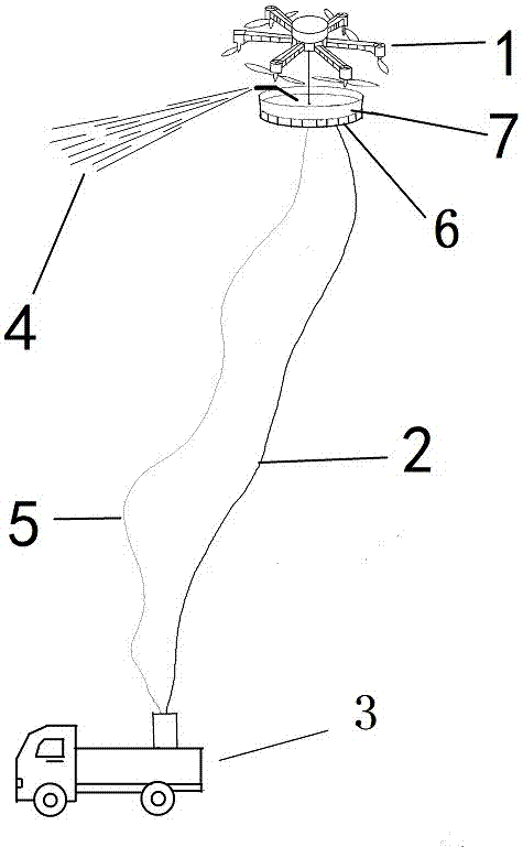
[0043] First prepare the pumps, pipes, and then make the rotorcraft. Make the frame first, install the motors on the frame (the number of motors is generally more than 3), and install the paddles on the motors. Then install the high barometer, GPS module, gyroscope, accelerometer sensor and various control circuits, remote control system, wire control system, manipulator, camera / monitoring system, etc.

[0044] Then the manned and cargo compartments etc. are installed in the lower part of the aircraft. And the control system of the aircraft is installed, which is convenient for personnel to control the aircraft.

[0045] Install the landing buffer system at the bottom of the aircraft.

[0046] Install safety ropes, external wires, and pipes.

[0047] Arrange the above equipment in the truck and fix it.

[0048]The above description is on...


PUM


Abstract

The invention discloses a fire fighting and rescue system comprising a vehicle body, a pump, a pipeline, a control system and an aircraft. According to the fire fighting and rescue system, the aircraft is adopted to pull up the pipeline, the height of fire extinguishment can reach 200-1000 m or above, and the construction cost of the system is low, specifically, the price of the system is much less than the price of a current high-grade fire fighting truck.

Description

technical field [0001] The invention belongs to the fire-fighting field, in particular to a fire-fighting and rescue system used for fire-fighting of high-rise and super-high-rise buildings. Background technique [0002] In recent years, famous high-rise building fires have occurred in Beijing, Shanghai, London and other places, and the fire protection problems of high-rise and super high-rise buildings have become increasingly serious. The consequences of high-rise building fires are very serious, mainly because their rescue is very difficult. At present, the fire fighting height of fire trucks is only more than 100 meters, which is about 30-50 storeys high. Contents of the invention [0003] Purpose of the invention: In order to solve the current fire-fighting and rescue problems of high-rise and super-high-rise buildings and avoid the disadvantages of the prior art, the present invention provides a fire-fighting and rescue system with a fire-extinguishing height of 200...

Claims


Application Information

Patent Timeline
IPC IPC(8): A62C3/02A62C31/03A62B1/00B64D1/18B64C27/08
CPCA62C3/0214A62B1/00A62C3/0242A62C31/03B64C27/08B64D1/18
Inventor 王淑妍杨卫国
Owner 苏州市皎朝纳米科技有限公司
Learn More