Pressure-reducing type unloading valve capable of emptying and manufacturing method thereof
A technology of unloading valve and pressure seat, applied in the field of water control equipment, to achieve the effect of high reliability
- Summary
- Abstract
- Description
- Claims
- Application Information
AI Technical Summary
Problems solved by technology
Method used
Image
Examples
Embodiment 1
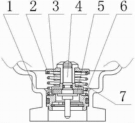
[0022] A method for manufacturing an evacuable decompression unloading valve, the unloading valve includes a zinc-manganese brass unloading valve main body 1, a pressure seat 2 matching the zinc-manganese brass unloading valve main body 1, and a limiting structure 6 , anti-fatigue and shock-resistant first spring 3 and the second spring 7 which rotates counter-rotatingly with the first spring 3 and is set in the first spring 3, the piston rod 4 set in the first spring 3 and the second spring 7, and the buffer Device 5, wherein the manufacturing method of the first spring 3 comprises the following steps:
[0023] 1) Pre-preparation
[0024] ① Select beryllium bronze QBe2.0 copper billet as the spring raw material;
[0025] ② Select forging equipment equipped with hydraulic generating device, rotary push device and air cooling device; select vacuum resistance furnace as initial forging heating equipment;
[0026] ③Select four forging hammer heads with 90° forging axes in seque...
Embodiment 2
[0036] The whole is consistent with Example 1, the difference is:
[0037] The manufacturing method of the first spring 3 comprises the following steps:
[0038] ① Heating the beryllium copper QBe2.0 billet through a vacuum resistance furnace to a value higher than its theoretical AC 3 At a temperature of 120°C, keep warm for (15d) min / mm according to the diameter of the copper billet, and then take it out of the furnace, and fix the bottom of the copper billet on the rotary push device;
[0039]②The forging hammer head linked with the rotary push device is pushed by the hydraulic generating device, and the copper billet is extruded into a forging billet with a nearly square cross-section at a feed rate of about 5% for each deformation and a final deformation ratio of 40% to deform the copper billet. The length of one forging deformation of the billet is one forging cycle. After the last forging in one cycle, the forging hammer head is fixed on the surface of the copper bille...
Embodiment 3
[0044] The whole is consistent with Example 1, the difference is:
[0045] The manufacturing method of the first spring 3 comprises the following steps:
[0046] ① Heating the beryllium copper QBe2.0 billet through a vacuum resistance furnace to a value higher than its theoretical AC 3 At a temperature of 130°C, keep warm for (17d) min / mm according to the diameter of the copper billet, and then take it out of the furnace, and fix the bottom of the copper billet on the rotary push device;
[0047] ②The forging hammer head linked with the rotary push device is pushed by the hydraulic generating device, and the copper billet is extruded into a forging billet with a nearly square cross-section at a feed rate of about 5% for each deformation and a final deformation ratio of 45% to deform the copper billet. The length of one forging deformation of the billet is one forging cycle. After the last forging in one cycle, the forging hammer head is fixed on the surface of the copper bill...
PUM
 Abstract
Description
Claims
Application Information
 - R&D
- Intellectual Property
- Life Sciences
- Materials
- Tech Scout
- Unparalleled Data Quality
- Higher Quality Content
- 60% Fewer Hallucinations
Browse by: Latest US Patents, China's latest patents, Technical Efficacy Thesaurus, Application Domain, Technology Topic, Popular Technical Reports.
© 2025 PatSnap. All rights reserved.Legal|Privacy policy|Modern Slavery Act Transparency Statement|Sitemap|About US| Contact US: help@patsnap.com

