
Brake energy recycling system based on flywheels

A technology of recovery system and flywheel, which is applied in the field of brake energy recovery system based on flywheel, can solve the problems of recovery of braking energy, failure of motor braking torque to meet the braking force demand of the whole vehicle, insufficient effectiveness, etc., and achieve strong applicability Effect

Active Publication Date: 2017-09-01
泰州市扬帆车件有限公司
View PDF5 Cites 3 Cited by
  • Summary
  • Abstract
  • Description
  • Claims
  • Application Information

AI Technical Summary

Problems solved by technology

At this stage, the effectiveness of the braking energy recovery system is insufficient, especially when the braking demand is large, the braking torque generated by the motor cannot meet the braking force demand of the whole vehicle. At this time, mechanical braking is required to intervene and provide additional braking Torque, resulting in waste of heat energy generated by mechanical braking
In addition, due to the limitation of the charging and discharging times of the power battery,

Method used


Image

  • Brake energy recycling system based on flywheels
  • Brake energy recycling system based on flywheels
  • Brake energy recycling system based on flywheels

Examples


Example Embodiment

[0049] The invention is basically divided into three parts: brake energy recovery structure, displacement transmission hydraulic system, and flywheel energy utilization. The implementation methods are as follows:

[0050] First analyze the whole.

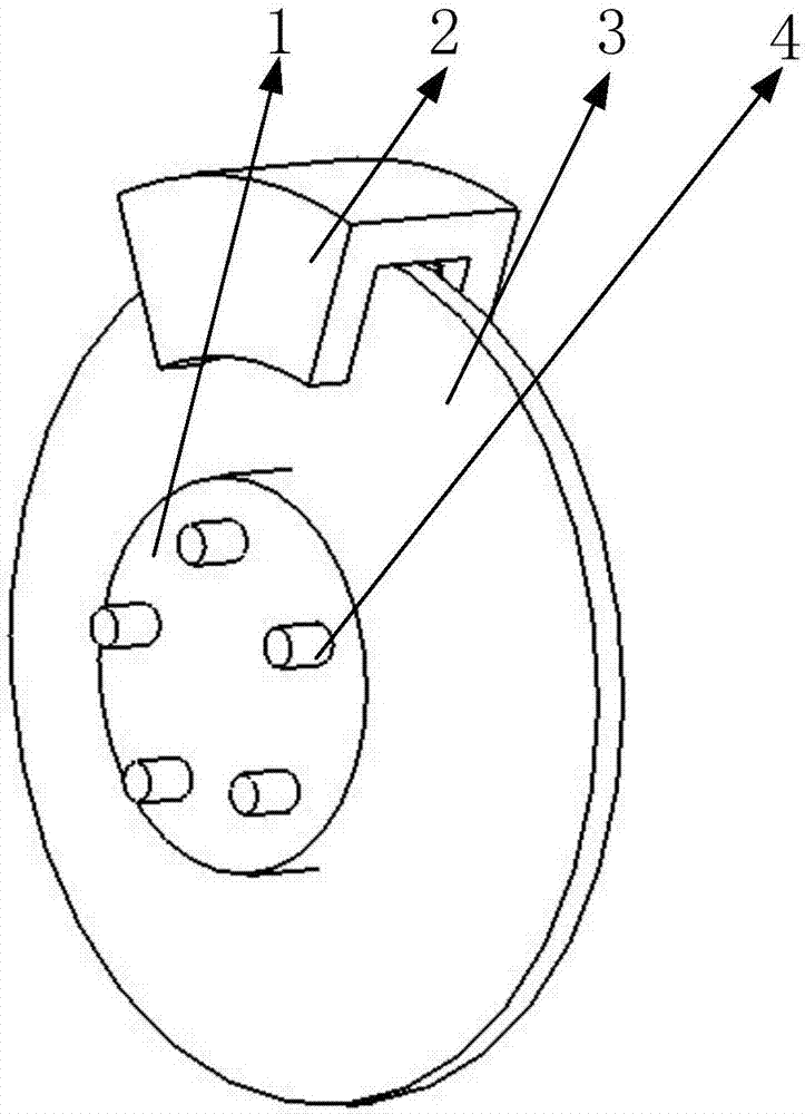
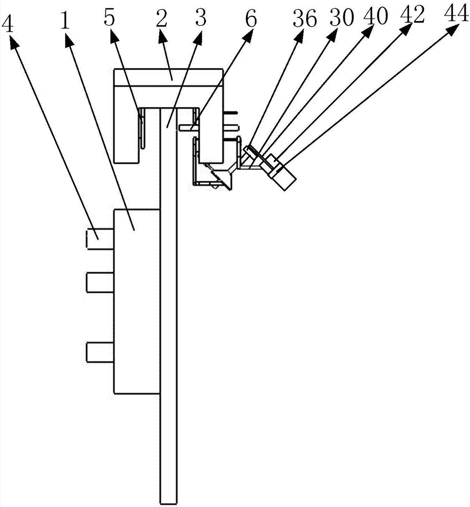
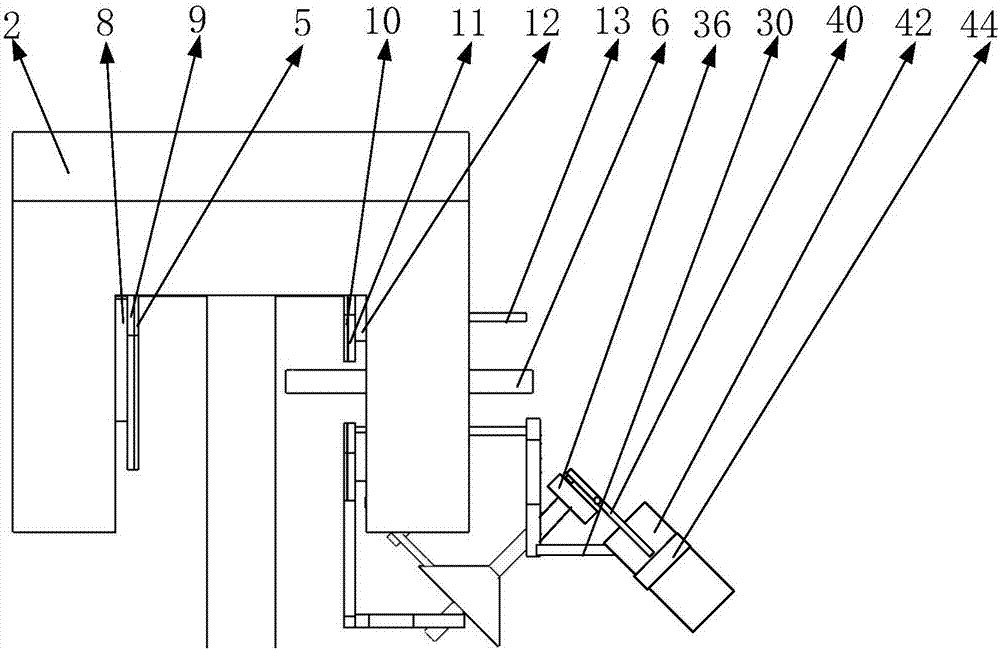
[0051] Such as Picture 12 As shown, the present invention includes a displacement transmission hydraulic system, a flywheel system, a brake energy recovery structure, a differential, an engine drive shaft, a differential wheel system, a synthetic drive shaft, and a wheel shaft. The brake energy recovery structure is mounted on the brake disc of the wheel Above, the flywheel system is connected with the brake energy recovery structure through the displacement transmission hydraulic system;

[0052] Such as Figure 13 As shown, the above-mentioned flywheel system includes a flywheel, a flywheel shaft, a clutch, and a flywheel clutch drive shaft. The flywheel is mounted on the flywheel shaft, and the flywheel shaft is connected to the flywhe...


PUM


Abstract

The invention belongs to the field of recycling brake energy of automobiles, and particularly relates to a brake energy recycling system based on flywheels. The recycling system comprises a displacement transferring hydraulic system, a flywheel system, a brake energy recycling structure, a differential mechanism, an engine transmission shaft, a differential wheel system, a combined transmission shaft, wheel shafts, and the like, wherein the brake energy recycling structure is installed on a wheel brake disc to turn the energy gained from the brake during a wheel braking process into rotating energy, the rotating energy is converted into reciprocating movement energy through a flywheel piston, and then the energy can be transferred to an energy storing flywheel by the displacement transferring hydraulic system. With hydraulic pipe transfer, the system is not limited by space and is good in applicability. The stored rotating energy of the flywheels is transferred to the wheel shafts when the automobile starts, and the purpose of saving oil while starting is realized.

Description

[0001] Technical field [0002] The invention belongs to the field of automobile braking energy recovery, in particular to a braking energy recovery system based on a flywheel. Background technique [0003] Since the beginning of the 21st century, energy and the environment have had an increasing impact on human life and social development. Energy-saving and emission-reduction technologies for transportation tools are becoming more and more prominent, energy recovery technology for vehicles has been given full attention, and braking energy recovery systems are widely used in electric vehicles and hybrid vehicles. [0004] At present, the basic principle of braking energy recovery for vehicles with braking energy recovery system is: during the braking process, the motor is used to generate electricity, and at the same time, the electric energy is stored in the power battery to realize the recovery and utilization of braking energy. At this stage, the effectiveness of the braki...

Claims


Application Information

Patent Timeline
IPC IPC(8): B60T1/10
Inventor 张蓉
Owner 泰州市扬帆车件有限公司
Learn More