Multifunctional armrest and stroller
A multi-purpose, armrest technology, applied in the direction of trolleys, multi-axle strollers/cradles, motor vehicles, etc., can solve the problems of single function, inconvenient movement of the whole vehicle, and can only be pushed from the back, etc., to achieve convenient use and structure. simple effect
- Summary
- Abstract
- Description
- Claims
- Application Information
AI Technical Summary
Problems solved by technology
Method used
Image

Examples
Embodiment 1
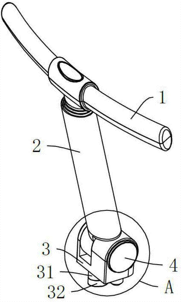
[0029] Embodiment one, see Figure 1 to Figure 3 , a multi-purpose handrail, comprising a handrail 1 and a pole 2, the handrail 1 is located at the top of the pole 2, and is characterized in that it also includes a mounting seat 3 and a gear adjustment device 4, and the bottom of the pole 2 passes through the gear The adjusting device 4 is hingedly connected with the mounting base 3 , and the gear position adjusting device 4 is used for adjusting the relative rotational position of the strut 2 and the mounting base 3 . When in use, as long as the multi-purpose handrail is installed on or near the seat cushion 6 of the cart, the gear adjustment device 4 is controlled to adjust the relative rotational position of the pole 2 and the mounting seat 3, so that the pole 2 is relatively seated. The pad 6 rotates, and when the pole 2 and the seat cushion 6 are perpendicular to each other, the multi-purpose armrest can be used as an armrest or as a pedal; by adjusting the angle, the car...
Embodiment 2
[0034] Embodiment two, see Figure 2 to Figure 4 , different from Embodiment 1, the bottom of the mounting seat 3 is provided with a through hole 36, and the outer wall of the through hole 36 is provided with a mounting hole 35, which can be installed on a cart provided with a cross bar 7, specifically, the cross bar 7 The rod 7 passes through the through hole 36, and the cross bar is connected with the mounting hole 35 with screws, so the structure is simple and the installation is firm.
[0035] In addition to one pole 2, it can also be set as two or more poles, so as to reduce the stress of a single pole 2 and have a longer service life, and the multiple poles 2 have the function of a guardrail. Embodiment three, see figure 2 , 3 , 5. The difference from Embodiment 1 and Embodiment 2 is that there are two support rods 2 .
[0036] A cart, including a frame body, wheels, and a seat cushion 6, characterized in that it also includes the above-mentioned multi-purpose armres...
Embodiment 4
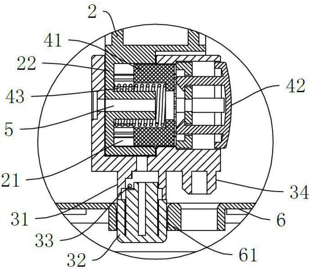
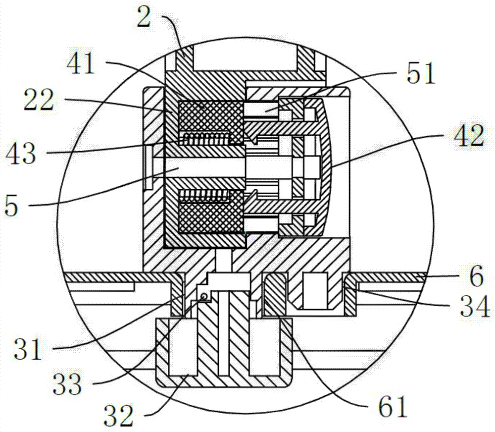
[0037] Embodiment four, see Figure 6 , 8 , 9, a kind of pushcart, comprises frame body, wheel, seat cushion 6, is characterized in that: also comprises the multi-purpose armrest described in embodiment one and embodiment three, described seat cushion 6 is provided with hole 61, so The shape of the hole 61 matches the outer wall of the protruding post 31 and the protruding post 31 passes through the hole 61 , and the seat cushion 6 is located between the mounting seat 3 and the protruding block 32 . During installation, it is only necessary to insert the bump 32 into the hole 61 on the seat cushion 6, the rotating mounting base 3 drives the bump 31 to align the bump 32, and the bump 31 is inserted into the hole 61, after which the bump 32 is restored to its original position by the retaining spring 33. Position, to achieve the installation of multi-purpose handrail, no tools, convenient and quick.
PUM
 Abstract
Description
Claims
Application Information