
A new pipeline robot

A pipeline robot and pipeline technology, applied in the field of new pipeline robots, can solve the problems of weak signal in metal pipes, difficult data interconnection, loss of master controller of pipeline robots, etc., and achieve the effects of wide application range, small size and exquisite structure

Active Publication Date: 2019-06-04
成都双创时代科技有限公司
View PDF8 Cites 0 Cited by
  • Summary
  • Abstract
  • Description
  • Claims
  • Application Information

AI Technical Summary

Problems solved by technology

[0006] In this patent application, it provides an intelligent remote-controlled pipeline robot. Although it includes universal transmission components, it can adapt to pipelines of various diameters, but if there are foreign objects in the pipeline, or the pipeline is bent or narrowed, etc. , the adaptability of the pipeline robot will be significantly weakened. Further, if it is in a metal pipe, the signal in the metal pipe is weak or it is difficult to communicate with the outside, the pipeline robot will lose its master controller, and it is difficult to be competent in various complex environments.

Method used


Image

  • A new pipeline robot
  • A new pipeline robot
  • A new pipeline robot

Examples


Embodiment 1

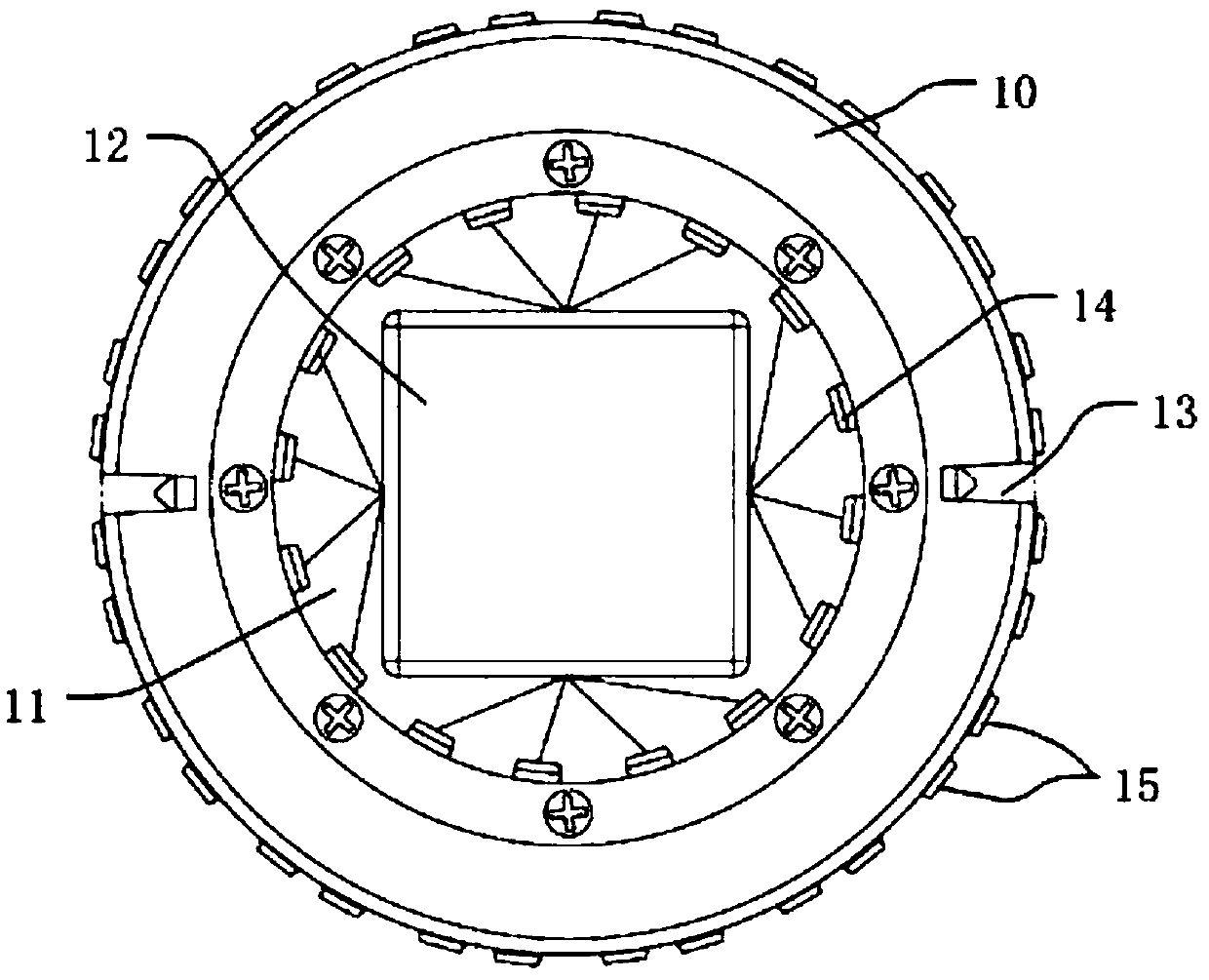
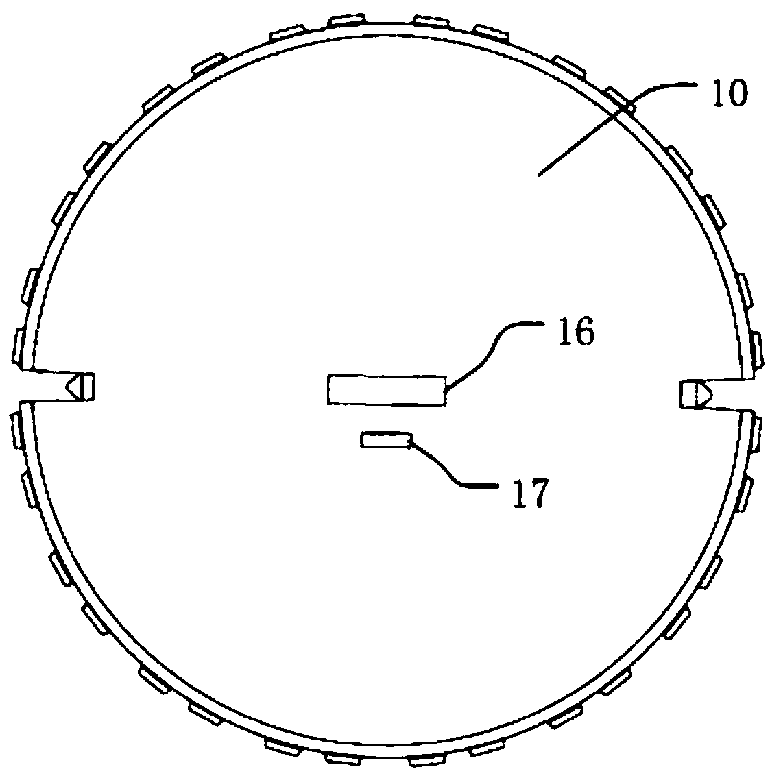
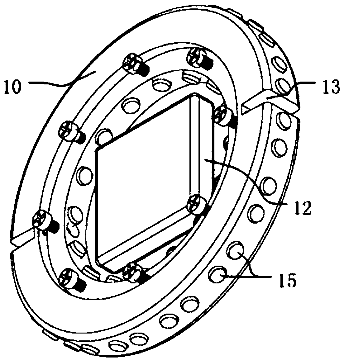
[0044] A new type of pipeline robot, see attached figure 1 - attached Figure 4 As shown, it includes a housing 10, a magnetic traveling device and a control mechanism 12;

[0045] The housing 10 is used to roll and travel in the pipeline; the housing 10 is a disc-shaped structure, and a concave circular groove 11 is provided in the middle of the front of the housing 10, and the annular side of the housing 10 is the first side, The annular inner wall of the circular groove 11 is the second side, and the first side is provided with mutually symmetrical camera gaps 13, and a camera 18 and an LED light 19 are also installed in each camera gap 13;

[0046]The magnetic force traveling device is used to provide the power for the rolling movement of the casing 10, and adjust the direction and position of the traveling by changing the magnitude of the magnetic force; Installed on the second side at equal intervals, the magnet groups 15 are installed on the first side at equal interv...

Embodiment 2

[0050] The difference between this embodiment and Embodiment 1 is that the magnet group 15 of the present embodiment is composed of a permanent magnet and an electromagnet, and the shapes of the permanent magnet and the electromagnet are both circular button shapes. This embodiment adopts this The combination of 15 magnet groups makes the magnetic force of one permanent magnet unable to fully bear the weight of the entire pipeline robot, and cannot be stably adsorbed on the inner wall of the pipeline, while the other electromagnet only needs to provide a small amount of magnetic force to achieve adsorption on the inner wall of the pipeline. purpose, and can achieve the purpose of advancing in the pipeline through the magnetic force conversion of different magnet groups 15.

Embodiment 3

[0052] The difference between this embodiment and the above two embodiments is that please refer to the attached Figure 5 And attached Figure 6 As shown, in this embodiment, tapered terminals 20 are respectively provided on the front of the housing 10 and the back of the housing 10 to prevent falls, and the tapered terminals 20 will not cause the phenomenon of falling when encountering obstacles during the pipeline robot’s travel. , will rotate around the tapered terminal 20 once, and continue to move forward;

[0053] The structure is exquisite, which avoids the disadvantages of traditional pipeline robots that cannot work normally after being dumped in the pipeline, and can work normally under harsh conditions such as foreign objects in the pipeline, pipeline bends, and pipeline narrowing.


PUM


Abstract

The invention relates to a novel pipeline robot which comprises a shell, a magnetic advancing device and a control mechanism. The shell is used for rolling to advance in a pipeline and is of a disc structure. Camera gaps are symmetrically reserved between the annular side faces of the shell, and a camera and an LED lamp are further installed in each camera gap. The magnetic advancing device is used for providing power for rolling advancing of the shell and adjusting the direction and location of advancing by changing the magnetic force. The control mechanism is used for sending a control command and providing electric energy for the magnetic advancing device. Advancing power is formed for the pipeline robot through changes of the magnetic force, and besides, as the pipeline robot is of a round structure, the robot can roll to advance in the pipeline continuously; as the magnetic force can be controlled to change, the robot can bypass barriers easily once encountering the barriers; and besides, the size of the pipeline robot can be reduced, and thus the pipeline robot is suitable for the task of routing inspection in various metal pipelines.

Description

technical field [0001] The invention relates to the technical field of robots, in particular to a novel pipeline robot. Background technique [0002] Pipeline robot is a kind of machine, electricity and instrument that can walk automatically along the inside or outside of a small pipeline, carry one or more sensors and operating machinery, and perform a series of pipeline operations under the remote control of the staff or the automatic control of the computer. system. There are eight types of existing pipeline robots, namely wheeled robots, crawler robots, abdominal wall robots, walking robots, peristaltic robots, screw-driven robots and snake-like robots, but the travel methods of these pipeline robots all exist. Some disadvantages are not only high power consumption, but also inconvenient operations such as cornering and cornering. [0003] Patent application number: 201710020863.9 discloses a crawler-type pipeline robot, including a body body, a traveling mechanism, a ...

Claims


Application Information

Patent Timeline
Patent Type & Authority Patents(China)
IPC IPC(8): F16L55/26F16L55/30F16L101/30
CPCF16L55/26F16L55/30F16L2101/30
Inventor 宋彬
Owner 成都双创时代科技有限公司
Learn More