Supercharge Your Innovation With Domain-Expert AI Agents!

Drawer type cooling device

A cooling device and drawer-type technology, applied in the field of metallurgy, can solve problems such as difficult disassembly, unsafe online disassembly, and inconvenient cleaning

Pending Publication Date: 2017-09-01
RUIAN FIRST VALVE FACTORY
View PDF13 Cites 0 Cited by
  • Summary
  • Abstract
  • Description
  • Claims
  • Application Information

AI Technical Summary

Problems solved by technology

[0003] In view of the deficiencies in the existing technology, the purpose of the present invention is to completely solve the defects of the existing technology such as difficult disassembly, unsafe online disassembly, heavy maintenance workload, inconvenient cleaning after internal dust compaction, etc., improve the equipment operation rate, reduce the Drawer Cooling Unit with Cost-effective and Shortened Troubleshooting Time

Method used


Image

  • Drawer type cooling device
  • Drawer type cooling device
  • Drawer type cooling device

Examples


Embodiment Construction

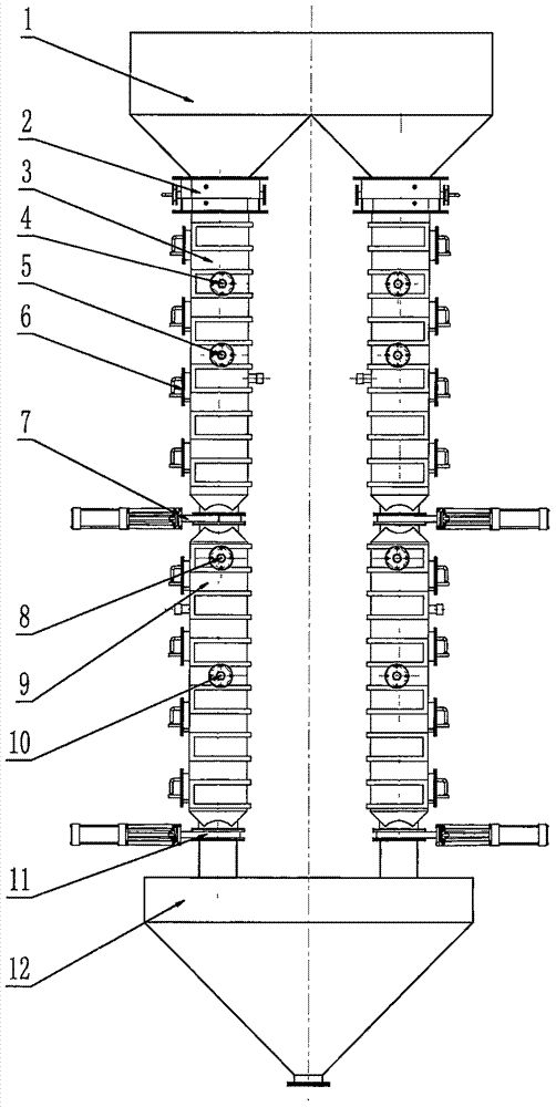
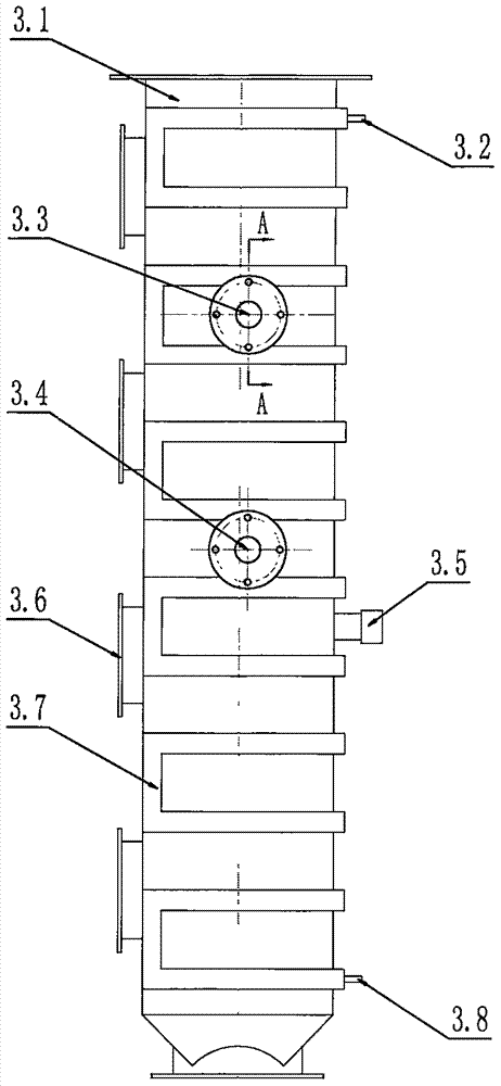
[0016] Such as figure 1 , figure 2 , image 3 , Figure 4 , Figure 7 As shown, the drawer-type cooling device includes an ash bin 1 and an ash discharge hopper 12. The bottom of the ash bin 1 of the primary dust removal system is connected with the upper cooling chamber 3 through the upper shut-off valve 2, and the lower part of the upper cooling chamber 3 passes through the middle The cut-off valve 7 is connected with the lower cooling chamber 9, and the bottom of the lower cooling chamber 9 is connected with the ash discharge hopper 12 through the lower cut-off valve 11; the upper cut-off valve 2 is normally open during normal use, and the middle cut-off valve Both the valve 7 and the lower cut-off valve 11 are in the closed state. When the particles and dust in the upper cooling chamber 3 have accumulated a certain amount, the middle cut-off valve 7 is opened. At this time, the lower cut-off valve 11 is in the closed state, and the particles and dust are discharged to ...


PUM


Abstract

The invention discloses a drawer type cooling device. The drawer type cooling device comprises an upper chamber, an upper shut-off valve, a lower chamber, a lower shut-off valve and N drawer type water coolers. By fully utilizing the floating falling characteristic of dust particles in the falling process, particle dust makes contact with multiple drawer type water coolers multiple times layer upon layer when the particle dust floats down, and then a full cooling effect is achieved; the drawer type cooling device is divided into the upper chamber and the lower chamber for temporary storage, the upper chamber and the lower chamber are isolated through a middle shut-off valve, and the lower chamber is isolated from a dust discharging bin through the lower shut-off valve; the exteriors of the whole chambers are provided with winding water pipes for cooling, and the drawer type water coolers can be freely disassembled. The drawer type cooling device has the advantages that overhauling is convenient, equipment can be overhauled and replaced on line, a coke dry quenching system does not need to be stopped, continues running of the coke dry quenching system can be guaranteed, and the condition that potential safety hazards exist when overhauling personnel conduct overhauling in a high-temperature and narrow space is eliminated.

Description

technical field [0001] The invention relates to a CDQ coke powder recovery device in the field of metallurgy and a high-temperature mineral powder recovery device for a dust collector of a sintering machine. As a system for collecting high-temperature particles and dust in one-time dust removal, the high-temperature particles and dust are collected in a drawer-type water-cooled collection device. Discharging after internal cooling, especially relates to a kind of ash slag heat exchange cooling device. Background technique [0002] In the CDQ coke powder recovery and sintering machine dust collector system, the high temperature coke powder needs to be cooled during recovery, and the CDQ water-cooled sleeve cooler is a special device for cooling the high temperature coke powder. The existing CDQ water-cooled casing cooler mainly includes a cooler body, a single fork on the top to collect CDQ powder, inner and outer casings located in the cooler body, water inlet, drainage syst...

Claims


Application Information

Patent Timeline
Patent Type & Authority Applications(China)
IPC IPC(8): F25D17/02
CPCF25D17/02
Inventor 陈秀林陈皓瑞张茂志竺秀连陈建青
Owner RUIAN FIRST VALVE FACTORY
Features
  • R&D
  • Intellectual Property
  • Life Sciences
  • Materials
  • Tech Scout
  • Unparalleled Data Quality
  • Higher Quality Content
  • 60% Fewer Hallucinations
Learn More