
Sniper system of unmanned aerial vehicle

A technology of unmanned aerial vehicles and targets, applied in radio wave measurement systems, electromagnetic wave re-radiation, measurement devices, etc., can solve problems such as unsuitable expulsion methods, loss of life and property, and major personal safety, so as to achieve precise strikes on targets, Effects of Avoiding Escape, Economically Hitting Targets

Inactive Publication Date: 2017-09-01
CHENGDU ANTI PHOTOELECTRIC TECH CO LTD
View PDF5 Cites 9 Cited by
  • Summary
  • Abstract
  • Description
  • Claims
  • Application Information

AI Technical Summary

Problems solved by technology

For example, some people use drones to secretly take pictures and steal information to obtain confidential information or privacy; they are even used by terrorists to carry substances that endanger public safety, such as explosives, which may cause serious personal safety
Another example is the recent black-flying of drones at many airports, which caused a large number of flights to be delayed and caused heavy losses. Fortunately, the drones did not carry dangerous substances, otherwise it would cause more serious loss of life and property
[0004] Most of the current drone countermeasure systems are aimed at deportation, but in many emergency scenarios, it is not suitable for deportation, especially when it is used by terrorists, it must be destroyed in time, otherwise it will lead to unimaginable consequences

Method used


Image

  • Sniper system of unmanned aerial vehicle
  • Sniper system of unmanned aerial vehicle
  • Sniper system of unmanned aerial vehicle

Examples


Embodiment Construction

[0015] The present invention will be further described in detail below in conjunction with examples and specific implementation methods. However, it should not be understood that the scope of the above subject matter of the present invention is limited to the following embodiments, and all technologies realized based on the content of the present invention belong to the scope of the present invention.

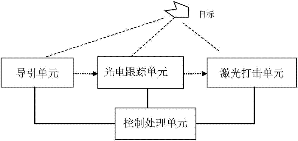
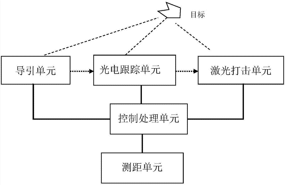
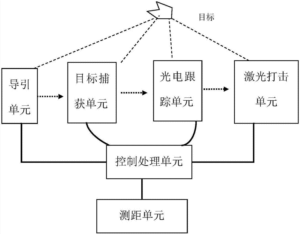
[0016] Such as figure 1 The schematic diagram of the UAV sniper system is shown. The system includes a control processing unit, a guidance unit, a photoelectric tracking unit and a laser strike unit.

[0017] Among them, the guidance unit mainly provides relevant information such as the movement and position of the target to be struck. The position information includes longitude, latitude and altitude, etc., and the movement information includes speed and acceleration. The guidance unit can be composed of single or multiple radars (including electromagnetic wave radar or laser ...


PUM


Abstract

The invention discloses a sniper system of an unmanned aerial vehicle. The sniper system comprises a control processing unit, a guide unit, a photoelectric tracking unit and a laser hitting unit, wherein the guide unit is mainly used for providing motion and position relevant information of a to-be-hit target; the control processing unit provides tracking used for the target to the photoelectric tracking unit; the photoelectric tracking unit is driven to continuously regulate an azimuth angle and a pitching angle according to position and position change position obtained by the guide unit, so that the to-be-hit target is locked; and the laser hitting unit is used for triggering a laser unit to output, so that the laser unit outputs laser for shooting the to-be-hit target once a hitting instruction is received, and therefore, the target is destroyed. According to the sniper system disclosed by the invention, a laser way is adopted to hit, so that an innocent third target can be prevented from being damaged; meanwhile, a laser way is adopted to hit hardly, so that horrible results can be prevented from being expanded. Meanwhile, the system can be directly in butt joint with an airport while interference is not generated on communication of the airport.

Description

technical field [0001] The invention relates to the field of UAV countermeasures, in particular to a UAV sniper system used to prevent UAVs from causing adverse consequences. Background technique [0002] UAV is an unmanned aircraft, which refers to an unmanned aircraft controlled by radio remote control equipment or its own program control device. With the rapid development of drone-related technologies, drones have been used in many fields. Due to the advantages of standing high, seeing far, and strong adaptability, UAVs can be matched with different mission loads, and are widely used in aerial photography, environmental monitoring, border monitoring, disaster search and rescue, geological survey and other fields. All walks of life are also competing to conduct research on the application of drones in their industry systems, and the era of "drone +" is quietly coming. [0003] However, with the explosive growth of the civilian drone market, the development of civilian dr...

Claims


Application Information

Patent Timeline
IPC IPC(8): F41H11/02G01S17/08
CPCF41H11/02G01S17/08
Inventor 袁桂俐
Owner CHENGDU ANTI PHOTOELECTRIC TECH CO LTD
Learn More