
Fault redundancy protection system and fault removal method for power electronic transformer

A power electronics and fault removal technology, applied in the fields of traction drive system and power system, can solve the problems of voltage and current shock, voltage loss of intermediate DC side, and the inability of redundant units to be put back into work quickly, so as to ensure normal operation, Control simplification and the effect of saving fault clearing time

Active Publication Date: 2019-04-05
BEIJING JIAOTONG UNIV
View PDF4 Cites 0 Cited by
  • Summary
  • Abstract
  • Description
  • Claims
  • Application Information

AI Technical Summary

Problems solved by technology

Due to the change of the number of operating units in the first scheme, voltage and current impacts will be generated during the fault removal process, and at the same time, very high requirements are required for the control system; the second scheme is simpler to control than the first scheme, and the voltage and current impacts Small, but when the power electronic transformer is running, the redundant unit will be input to the AC / DC side for bypassing, causing the intermediate DC side voltage to lose power, so that the redundant unit cannot be put into operation quickly

Method used


Image

  • Fault redundancy protection system and fault removal method for power electronic transformer
  • Fault redundancy protection system and fault removal method for power electronic transformer
  • Fault redundancy protection system and fault removal method for power electronic transformer

Examples


Embodiment Construction

[0031] The present invention will be described in further detail below in conjunction with the accompanying drawings. It should be emphasized that the following description is only exemplary and not intended to limit the scope of the invention and its application.

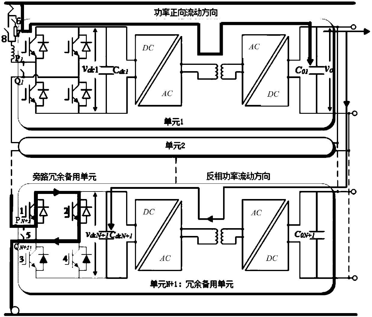
[0032] figure 1 It is a schematic diagram of the power electronic transformer fault redundancy protection system. The power electronic traction transformer is composed of N power conversion units with input in series and output in parallel. Each power conversion unit is composed of an H-bridge converter and a DC / DC converter. . The power electronic transformer fault redundancy protection system includes N power conversion units and 1 redundant backup unit, each unit includes an H-bridge converter and a medium / high frequency isolated DC / DC converter, redundant The circuit structure of the remaining backup units is the same as that of the power conversion unit; the first N units are power conversion units, and the ...


PUM


Abstract

The invention relates to a fault redundancy protection system and a fault removal method of a power electronic transformer. The system adopts N power conversion units and 1 redundant backup unit, N+1 units are input in series and output in parallel, and the H-bridge converter of the redundant backup unit passes through the input bypass contactor or a pair of upper switches tube, or the lower switching tube to bypass the entire redundant backup unit, the DC / DC converter of the redundant backup unit works in the power reverse mode, and charges the DC support capacitor on the output side of the H-bridge converter to maintain voltage stability . The fault removal method of the present invention includes three parts: isolation of the faulty unit, control switching of the H-bridge converter of the redundant backup unit, and control switching of the DC / DC converter of the redundant backup unit. The invention can effectively improve the stability and reliability of the DC / DC converter, reduce the electrical impact during the fault switching process, simplify the operation complexity of fault removal, and realize the safe and reliable fault redundancy protection of the power electronic transformer.

Description

technical field [0001] The invention relates to the field of traction drive system and electric power system, in particular to a fault redundancy protection system and a fault removal method of a power electronic transformer. Background technique [0002] The traction drive system is the energy source of the traction power system and auxiliary power supply system of high-speed EMUs, and is one of the core systems of high-speed EMUs. It needs to use power frequency transformers to convert high-voltage AC power into low-voltage power to obtain electrical energy. In the field of power systems, industrial frequency transformers are also needed to convert the high-voltage transmitted electric energy into low-voltage electricity for use by users. However, industrial frequency transformers have large volume and weight, low efficiency, and low power density, which increases energy consumption and maintenance costs. At the same time, the power factor and output voltage are uncontroll...

Claims


Application Information

Patent Timeline
Patent Type & Authority Patents(China)
IPC IPC(8): H02M1/32
CPCH02M1/32H02M1/0074H02M1/325
Inventor 刘建强赵楠杨景熙张捷频
Owner BEIJING JIAOTONG UNIV
Learn More