

A method for laying and forming powder bed multi-material areas
A process method and multi-material technology, applied in the field of multi-material additive manufacturing, can solve the problems of high equipment space occupancy rate and type restrictions, and achieve the effects of low cost, prevention of agglomeration and agglomeration, and simple process steps.
- Summary
- Abstract
- Description
- Claims
- Application Information
AI Technical Summary
Problems solved by technology
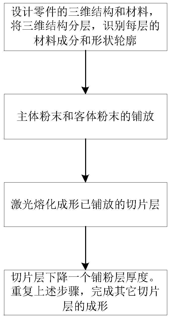
Method used
Image


Examples
Embodiment 1
[0044] Using the method of the present invention to prepare stainless steel parts with a nickel wear-resistant coating on the surface, the specific steps are as follows:
[0045] (1) Design the three-dimensional distribution of the coating on the inner and outer surfaces of the stainless steel parts according to the thickness requirements of the wear-resistant coating, and the coating thickness is 2mm. Layer processing along the processing direction, slice and identify each layer of information. The information of the nickel component area is stored in the mobile ultrasonic vibration micro powder feeding system, and the stainless steel component information is stored in the SLM main equipment control system.
[0046] (2) According to the material distribution results of each slice layer section, compile the relative motion program of the ultrasonic vibration micro powder feeding system in the XY plane; place the spherical stainless steel powder in the powder feeding cylinder and the...
Embodiment 2
[0051] Using the method of the present invention to prepare nickel-based superalloy parts with alumina thermal barrier coating on the surface, the specific steps are as follows:
[0052] (1) Design the three-dimensional distribution of the coating on the inner and outer surfaces of the nickel-based superalloy parts according to the thickness requirements of the thermal barrier coating, and the thickness of the coating is 20mm. Perform layering processing along the processing direction, slice and identify the information of each layer. The information of the area containing the alumina composition is stored in the mobile ultrasonic vibration micro powder feeding system 1, and the information of the nickel-based superalloy composition is stored in the SLM main equipment control system .
[0053] (2) According to the material distribution results of each slice layer section, compile the relative motion program of the ultrasonic vibration micro powder feeding system in the XY plane; pl...
Embodiment 3
[0058] Using the method of the present invention to prepare a pure titanium porous scaffold with a biocompatible niobium coating on the surface, the specific steps are as follows:
[0059] (1) Design the three-dimensional distribution of the coating on the inner and outer surfaces of the pure titanium porous stent according to the thickness of the niobium coating. The thickness of the coating is 5mm. The layered processing is carried out along the processing direction, and the information of each layer is sliced and identified. The information of the area containing the niobium content is stored in the mobile ultrasonic vibration micro powder feeding system, and the information of the pure titanium content is stored in the SLM main equipment control system.
[0060] (2) According to the material distribution results of each slice layer section, write the relative motion program of the ultrasonic vibration micro powder feeding system in the XY plane; place the spherical pure titani...
PUM
| Property | Measurement | Unit |
|---|---|---|
| particle diameter | aaaaa | aaaaa |
| particle diameter | aaaaa | aaaaa |
| thickness | aaaaa | aaaaa |
Abstract
Description
Claims
Application Information