Automatic feeding device for preassembled movable vanes

An automatic feeding and pre-assembly technology, applied in metal processing, metal processing equipment, manufacturing tools, etc., can solve the problems of time-consuming, labor-intensive, insufficient automation, etc., to avoid inaccurate moving distance and accurate moving distance Effect

Inactive Publication Date: 2017-09-05
UNIV OF SHANGHAI FOR SCI & TECH
View PDF7 Cites 2 Cited by
  • Summary
  • Abstract
  • Description
  • Claims
  • Application Information

AI Technical Summary

Problems solved by technology

The degree of automation of such a production method is seriously insufficient, which not only consumes manpower and time, but also is not conducive to the automatic connection of the entire production line.

Method used


Image

  • Automatic feeding device for preassembled movable vanes
  • Automatic feeding device for preassembled movable vanes

Examples


Embodiment Construction

[0016] The specific embodiments of the present invention will be described below with reference to the drawings and embodiments.

[0017]

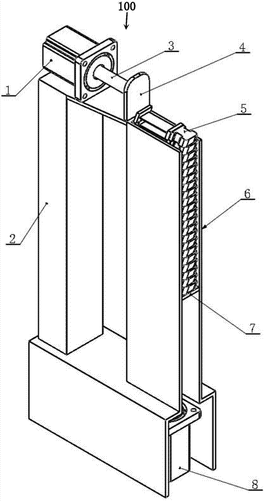
[0018] figure 1 It is a schematic diagram of the three-dimensional structure of the pre-assembled bucket automatic feeding device according to the embodiment of the present invention.

[0019] Such as figure 1 As shown, the pre-assembled moving blade automatic feeding device 100 is used to pre-assemble the moving blade 5, and includes a first motor 1, a support base 2, a first push rod 3, a first push plate 4, and a moving blade conveying chamber 6. The second motor 8, the push rod 9, and the control part (not shown in the figure).

[0020] The support base 2 is L-shaped, and has a horizontal part whose bottom surface is fixed on the ground and a vertical part which is vertically fixed on one end of the horizontal part.

[0021] The first motor 1 is fixed on the top of the vertical part of the support base 2, and the first push rod 3 is installed ...


PUM


Abstract

The invention provides automatic feeding equipment for preassembled movable vanes. The equipment is characterized by comprising a supporting seat, a first motor, a first push rod, a first push plate, a movable vane conveying chamber, a second motor, a second push rod, a second push plate and a control part; the supporting seat comprises a horizontal part and a vertical part; the first motor is fixed at the top of the vertical part; the first push rod is mounted at the output end of the first motor; the first push plate is mounted at one end, far away from the first motor, of the first push rod; the movable vane conveying chamber is shaped like a vertically extending groove and is used for accommodating the movable vanes; the second motor is arranged below the movable vane conveying chamber; the second push rod is mounted at the output end of the second motor; the second push plate is located inside the movable vane conveying chamber and carries the movable vanes; the bottom of the first push plate is higher than the top of the movable vane conveying chamber; the control part controls the second motor to drive the second push plate to move upwards, so that the movable vanes are sequentially pushed out of the top of the movable vane conveying chamber; and the control part controls the first motor to drive the first push plate to move in the horizontal direction, so that the movable vanes located at the top of the movable vane conveying chamber are pushed into a vane groove.

Description

Technical field [0001] The invention belongs to the field of steam turbine equipment manufacturing, and relates to a pre-assembled moving blade automatic feeding device. Background technique [0002] A steam turbine is a power machine that converts steam power into rotating mechanical energy. It is mainly composed of a stator and a rotor. Among them, the rotor is driven by the high temperature steam to rotate to drive the main shaft to rotate, which is an important part of the steam turbine. [0003] The rotor of a steam turbine generally includes an impeller mounted on the main shaft and a bucket mounted on the impeller. The moving blades have different shapes, and currently commonly used is the T-shaped root moving blade with a T-shaped root position (ie, the root of the leaf). [0004] The impeller is provided with a plurality of blade grooves arranged along the axial direction of the rotor for installing the moving blades. When installing the moving blades, pre-assembly is req...

Claims


Application Information

Patent Timeline
Patent Type & Authority Applications(China)
IPC IPC(8): B23P19/02
CPCB23P19/001B23P19/004B23P19/02
Inventor 王佳茂梅洁于忠海王启明王顺利王文韬
Owner UNIV OF SHANGHAI FOR SCI & TECH
Why Eureka
Try Eureka