Printing ink box

A technology for ink cartridges and ink storage, which is applied in printing and other fields, and can solve problems such as inability to solve residual ink problems, reduced ink capacity, etc.

Active Publication Date: 2017-09-05
MAIBO HIGH POLYMER MATERIAL NINGBO
View PDF10 Cites 1 Cited by
  • Summary
  • Abstract
  • Description
  • Claims
  • Application Information

AI Technical Summary

Problems solved by technology

This kind of ink cartridge reduces the amount of residual ink as a whole, but it still cannot solve the problem of residual ink in the lower layer of h...

Method used


Image

  • Printing ink box
  • Printing ink box
  • Printing ink box

Examples


Embodiment 1

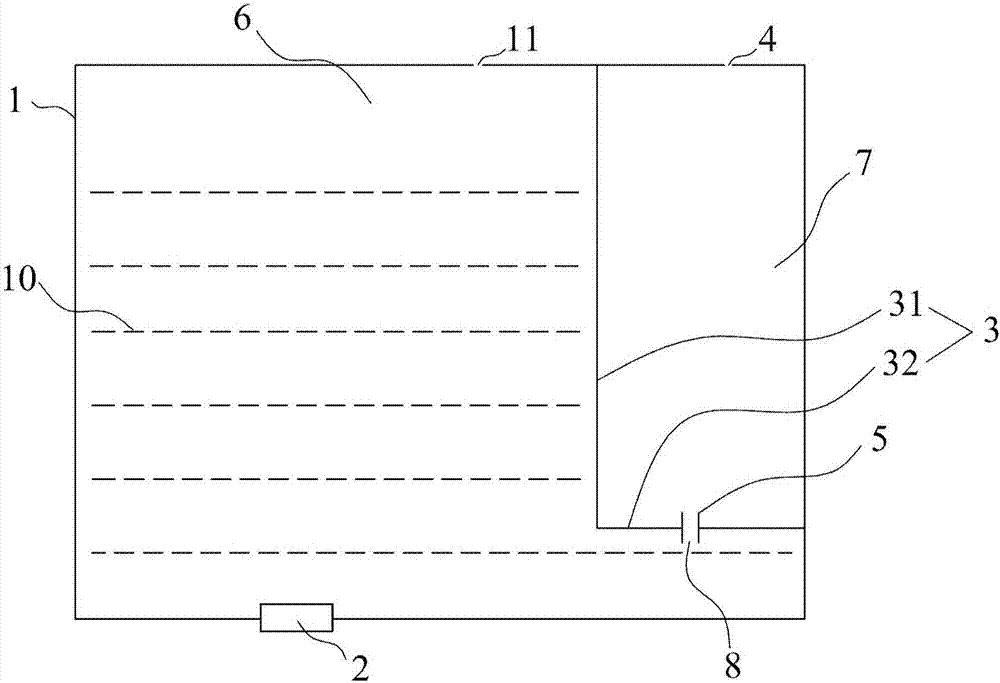
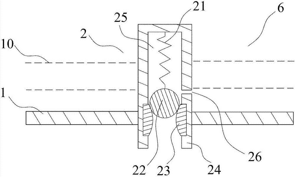
[0067] see Figure 1 to Figure 1BAs shown, in the first embodiment of the present invention, the printing ink cartridge of the present invention includes a housing 1, an ink outlet device 2, a partition wall 3, an air guide channel 4 and a gas-liquid exchange device 5, and the inner cavity of the housing 1 is arranged There is an ink chamber 6, the ink outlet device 2 is arranged at the bottom of the ink chamber 6, the partition wall 3 is arranged in the inner chamber of the housing 1 so as to divide the inner chamber of the housing 1 into the ink chamber 6 and the buffer chamber 7, and the air guide channel 4 is arranged on the housing 1 and communicates with the buffer chamber 7 and the outside atmosphere. In this embodiment, the air guide channel 4 is an air guide hole, the gas-liquid exchange device 5 has a capillary channel 8, and the gas-liquid exchange device 5 is arranged on the partition wall 3 Among them, the ink chamber 6 communicates with the buffer chamber 7 throu...

Embodiment 2

[0071] see Figure 2A As shown, the structure and working principle of the second embodiment of the present invention are similar to that of embodiment 1, the difference is that the core body 9 of the gas-liquid exchange device 5 of the present embodiment is a single piece, which is a nylon 6 cylinder with ribs, And the capillary channel 8 is directly established in the middle hole of the nylon 6 cylinder, specifically, the inner wall of the middle hole of the nylon 6 cylinder is formed by arranging ribs facing inward. The capillary channel 8 has a length of 1 mm and an inner diameter of 0.5 mm, such as Figure 2A shown. The ink cartridge of Example 2 is more convenient to manufacture and has lower cost.

[0072] The shape, length, thickness and width of the capillary channel 8 can be adjusted according to the printing system's requirements for controlling the pressure in the ink chamber 6 . According to the stability requirements of the ink 10 and the viscosity and surface...

Embodiment 3

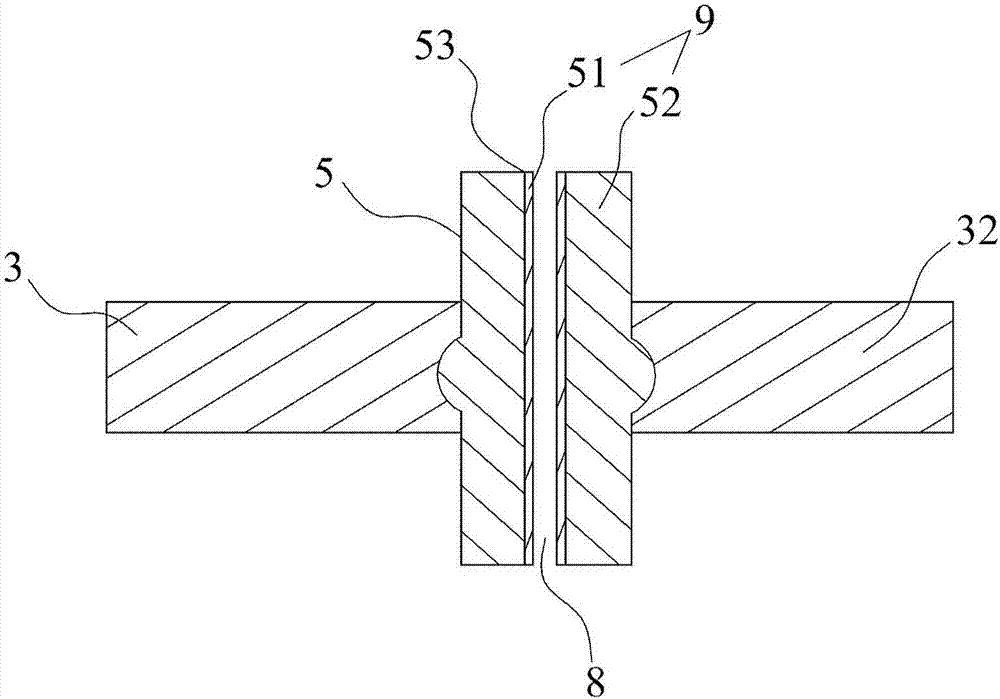
[0074] see Figure 3A and Figure 3B As shown, the structure and working principle of the third embodiment of the present invention are similar to those of the first embodiment, the difference lies in the design of the gas-liquid exchange device 5 . Figure 3A It is a front sectional view of the gas-liquid exchange device 5, Figure 3B It is a top view of the gas-liquid exchange device 5. In the present embodiment, the first core body 51 of the core body 9 of the gas-liquid exchange device 5 is a ceramic cylinder with a diameter of 3 millimeters. The partition wall 32) is integrally formed, or it can be considered that the second core body 52 is a part of the partition wall 3. For the sake of clarity, a part of the outline of the second core body 52 is outlined with a dotted line, and the inner wall of the through hole 53 of the second core body 52 is in the An annular gap is respectively designed on the opposite sides, and forms two capillary channels 8 with the ceramic cyl...


PUM

PropertyMeasurementUnit
Lengthaaaaaaaaaa
Thicknessaaaaaaaaaa
Diameteraaaaaaaaaa

Abstract

The invention provides a printing ink box. The printing ink box comprises a shell, partition walls, an ink cavity, a buffer chamber, an air guide channel, an air-liquid exchange device and an ink outlet device, wherein the partition walls divide an inner cavity of the shell into the ink cavity and the buffer chamber; the ink outlet device is arranged at the bottom of the ink cavity; the air guide channel arranged on the shell communicates with the outside atmosphere and the buffer chamber; the air-liquid exchange device with a capillary channel is disposed in one of the partition walls or between the partition walls and the shell; and the capillary channel communicates with the ink cavity and the buffer chamber. The air-liquid exchange device is further provided with a core, and the capillary channel is disposed in the core. The core can further comprise a first core body and a second core body, and the capillary channel is disposed in the first core body or between the first core body and the second core body. The printing ink box is simple in structure, stable in property, large in ink content and small in residual ink amount, and wastes and environmental pollution are reduced.

Description

technical field [0001] The invention relates to the technical field of electronic products, in particular to the technical field of printing, and specifically refers to a printing ink cartridge. Background technique [0002] Inkjet printing is a relatively mature and widely used printing technology. Whether bubble or piezoelectric printing technology is used, the inkjet printing system generally needs to use a certain method to stably and controllably transport the liquid medium to be printed. to the print head. The commonly used method is to create a certain negative pressure in the ink cartridge, the ink in the ink cartridge is transported to the print head under the action of the suction force of the print head during printing, and at the same time, the negative pressure can effectively keep the ink in the ink cartridge without leakage . [0003] Various methods can be used to create the negative pressure in the ink cartridge, for example, using a mechanical valve to cr...

Claims


Application Information

Patent Timeline
IPC IPC(8): B41J2/175
CPCB41J2/17513B41J2/17556
Inventor 王立平周兴夫王立娟
Owner MAIBO HIGH POLYMER MATERIAL NINGBO
Why Eureka
Try Eureka