Laptop positioning rotary shaft

A notebook computer and positioning shaft technology, applied in pivot connection, engine components, engine lubrication, etc., can solve the problems of easy melting of lubricating oil in the oil tank, difficult formation of oil film, slow heat dissipation, etc., to ensure the continuity and stability of lubrication , high fixing strength and stability, prolonging the service life

Active Publication Date: 2017-09-05
KUNSHAN KERSEN SCI & TECH
View PDF7 Cites 3 Cited by
  • Summary
  • Abstract
  • Description
  • Claims
  • Application Information

AI Technical Summary

Problems solved by technology

[0003] In the prior art, the rotating shaft of a notebook computer is generally provided with an annular oil guide groove directly on the pivot of the rotating shaft, and the rotating shaft is made of zinc alloy. This design has the following disadvantages: the rotating shaft of a notebook computer with this structure has slow heat dissipation, There will be local heating, and the lubricating oil in th

Method used


Image

  • Laptop positioning rotary shaft
  • Laptop positioning rotary shaft
  • Laptop positioning rotary shaft

Examples


Embodiment 1

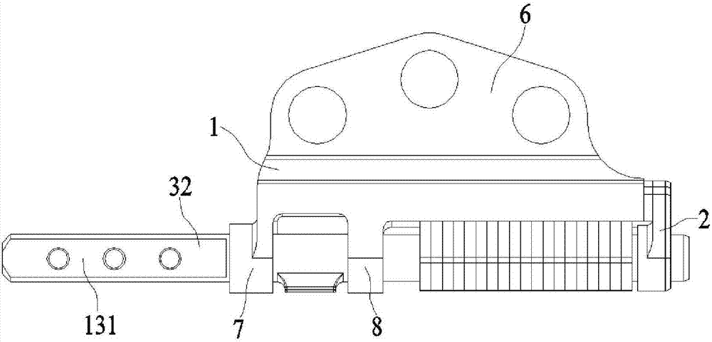
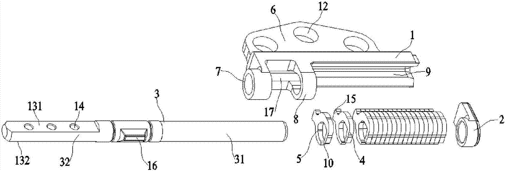
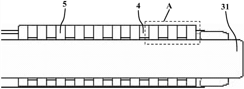
[0028] Embodiment 1: A positioning shaft for a notebook computer, including a rotating bracket 1, a stopper 2, a shaft core rod 3, several loose fin rings 4 and several tight fin rings 5, and the rotating bracket 1 further includes a support 6, the first bushing 7 and the second bushing 8, the first bushing 7 is located at one end of the lower end surface of the rotating bracket 1, the second bushing 8 is located at the middle of the lower end surface of the rotating bracket 1, and the rotating There is a dove-shaped groove 9 on the lower end surface of the bracket 1 between the other end and the second bushing 8. One side of the shaft core rod 3 is a polished rod portion 31, and the other side is a non-polished rod portion 32. The polished rod part 31 of the core rod 3 is embedded in the first bushing 7 and the second bushing 8 of the support part 6, and the lower part and the upper part of the stopper 2 are respectively fitted in the end of the polished rod part 31 and the do...

Embodiment 2

[0032] Embodiment 2: A positioning shaft for a notebook computer, including a rotating bracket 1, a stopper 2, a shaft core rod 3, several loose fin rings 4 and several tight fin rings 5, and the rotating bracket 1 further includes a support 6, the first bushing 7 and the second bushing 8, the first bushing 7 is located at one end of the lower end surface of the rotating bracket 1, the second bushing 8 is located at the middle of the lower end surface of the rotating bracket 1, and the rotating There is a dove-shaped groove 9 on the lower end surface of the bracket 1 between the other end and the second bushing 8. One side of the shaft core rod 3 is a polished rod portion 31, and the other side is a non-polished rod portion 32. The polished rod part 31 of the core rod 3 is embedded in the first bushing 7 and the second bushing 8 of the support part 6, and the lower part and the upper part of the stopper 2 are respectively fitted in the end of the polished rod part 31 and the do...


PUM


Abstract

The invention discloses a laptop positioning rotary shaft. A rotary bracket of the laptop positioning rotary shaft further comprises a supporting part, a first shaft sleeve and a second shaft sleeve. The area, between the other end of the rotary bracket and the second shaft sleeve, of the lower end face of the rotary bracket is provided with a dove-shaped groove. Loose fin rings and tight fin rings are each provided with a notched groove. A smooth rod part of an axis rod is sleeved with the loose fin rings and the tight fin rings. Gaps are reserved between the loose fin rings and the smooth rod part, and the tail ends of the loose fin rings are in tight fit contact with the smooth rod part. The inner walls of the loose fin rings and the tight fin rings are each provided with two inward sunken grooves which are separately located in the two sides of the corresponding notched groove. The gap part of each loose fin ring communicates with the two inward sunken grooves of the corresponding loose fin ring. The loose fin rings and the tight fin rings are alternately arranged. The middle area between the smooth rod part and the unsmooth rod part of the axis rod is provided with a protruding strip. The laptop positioning rotary shaft is good in stability and uniformity of torsion and friction force, and floating of the torsion and the friction force are controlled within 7%, so that torsion attenuation is reduced, and lubrication continuity and durability between the smooth rod part and the inner walls of the fin rings are further ensured.

Description

technical field [0001] The invention relates to a positioning rotating shaft for a notebook computer, in particular to a computer positioning rotating shaft used between a liquid crystal screen board and a mainboard of a notebook computer. Background technique [0002] With the development of science and technology, various electronic products continue to appear, which bring great changes to people's lives, especially the use of computers has changed people's lifestyles and accelerated their pace of life. In the past two decades, with the development of material science and the emergence of smaller integrated chips, computers have evolved into a notebook computer that is small in size, thin in thickness, light in weight and easy to carry around. Most of the existing notebooks are of flip-top type. In order to meet the design considerations of thinness, smallness and light weight, they are generally designed to be composed of two parts: the base composed of the host body and ...

Claims


Application Information

Patent Timeline
IPC IPC(8): F16C11/04F16N1/00
CPCF16C11/04F16N1/00
Inventor 徐金根郑吉昌
Owner KUNSHAN KERSEN SCI & TECH
Why Eureka
Try Eureka