
Drum type brake

A technology of drum brakes and brake drums, which is applied in the direction of hydraulic drum brakes, brake actuators, gear transmission mechanisms, etc., can solve the problems of slow movement, complicated maintenance, and failure to provide braking force, so as to improve the braking force , high efficiency, good maintenance effect

Inactive Publication Date: 2017-09-05
防城港市海洋局
View PDF5 Cites 2 Cited by
  • Summary
  • Abstract
  • Description
  • Claims
  • Application Information

AI Technical Summary

Problems solved by technology

[0003] However, the brakes used on mobile devices in the prior art, such as automobiles, mostly use mechanical brakes, that is, provide braking force through mechanical power, resulting in insufficient braking force, correspondingly slow action, and complicated maintenance

Method used


Image

  • Drum type brake
  • Drum type brake

Examples


Embodiment Construction

[0028] In order to enable those skilled in the art to better understand the technical solutions of the present invention, the present invention will be described in detail below in conjunction with the accompanying drawings and specific embodiments.

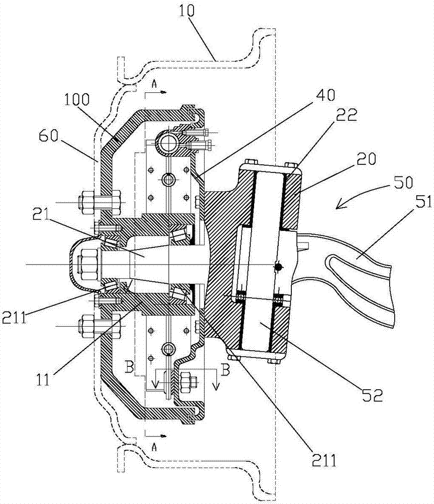
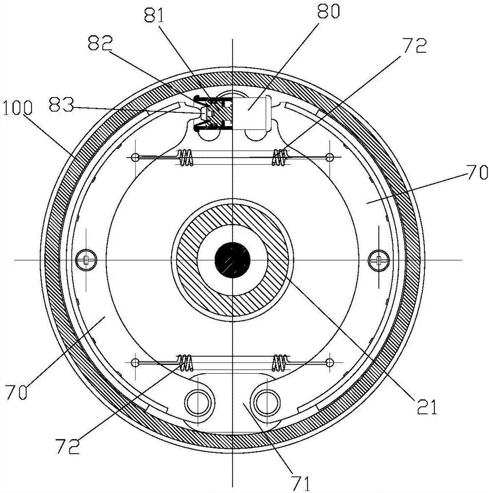
[0029] Such as figure 1 and figure 2 As shown, the embodiment of the present invention discloses a drum brake, which is used for braking the wheel hub 10 of an automobile. The drum brake includes: a fixed ring, a steering body 20, an annular elastic disc 40, a bogie 50, Shaped brake drum 70 and brake cylinder 80. The fixed ring is coaxial and fixedly connected with the hub 10, and the center of the fixed ring is formed with a mounting sleeve 11; the steering body 20 is fixed with a mandrel 21, and the steering body 20 is provided with a steering hole, and the mandrel 21 It extends into the installation sleeve 11 and is rotatably connected with the installation sleeve 11; the inner edge of the annular elastic disc 40 is fixedly...


PUM


Abstract

The invention discloses a drum brake, which is used for braking a wheel hub, comprising: a fixed ring; a steering body; an annular elastic disc; a bogie; two arc-shaped brake drums; and a brake oil cylinder. The present invention provides the braking force through the brake oil cylinder, thereby improving the braking force. Compared with the brakes in the prior art that use mechanical power as the braking force, the present invention uses hydraulic pressure as the power to provide the braking force, which has high efficiency and long service life of the brake. Better maintenance.

Description

technical field [0001] The invention relates to the technical field of braking, in particular to a drum brake. Background technique [0002] A brake is a device that has the functions of decelerating, stopping or keeping a moving part (or moving machinery) in a stopped state. It is a mechanical part that stops or slows down the moving parts in the machine. Commonly known as brakes, brakes. The brake is mainly composed of frame, brake parts and operating device. Some brakes are also equipped with an automatic adjustment device for the clearance of the brake parts. In order to reduce the braking torque and structural size, the brake is usually installed on the high-speed shaft of the equipment, but for large-scale equipment with high safety requirements (such as mine hoists, elevators, etc.), it should be installed on the low-speed shaft close to the working part of the equipment. superior. Brakes (brake staff) can be divided into two categories, industrial brakes and aut...

Claims


Application Information

Patent Timeline
IPC IPC(8): F16D51/24F16D65/14
CPCF16D51/24F16D65/14F16D2121/04F16D2125/06F16D2125/08
Inventor 何祥英
Owner 防城港市海洋局
Features
  • Generate Ideas
  • Intellectual Property
  • Life Sciences
  • Materials
  • Tech Scout
  • Unparalleled Data Quality
  • Higher Quality Content
  • 60% Fewer Hallucinations
Learn More