Processing machine with rotating tool holder

A technology of processing machinery and rotary tool holder, applied in metal processing machinery parts, metal processing equipment, manufacturing tools, etc., can solve the problems of complex production process and increase cost, and achieve the effect of small rotation quality

Inactive Publication Date: 2017-09-08
陈芬芬
View PDF3 Cites 1 Cited by
  • Summary
  • Abstract
  • Description
  • Claims
  • Application Information

AI Technical Summary

Problems solved by technology

[0004] The technical problem to be solved by the present invention is to overcome some difficulties such as complicated production process and increased cost at the same time, and provide a processing machine for rotary tool rest, so as to solve the above-mentioned problems

Method used


Image

  • Processing machine with rotating tool holder
  • Processing machine with rotating tool holder
  • Processing machine with rotating tool holder

Examples


Embodiment

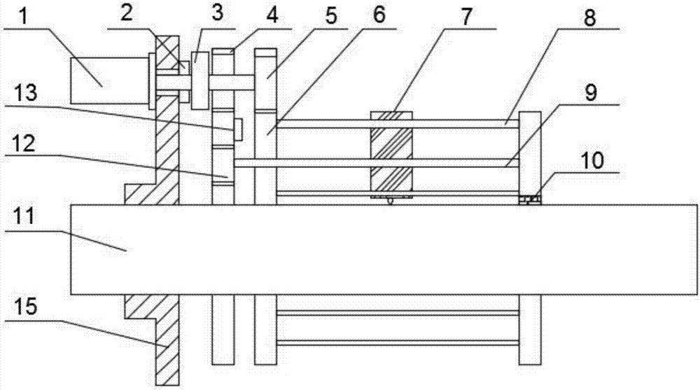
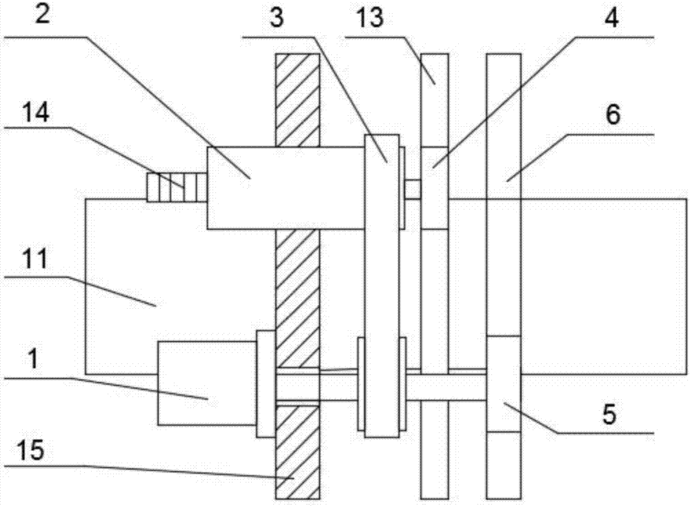
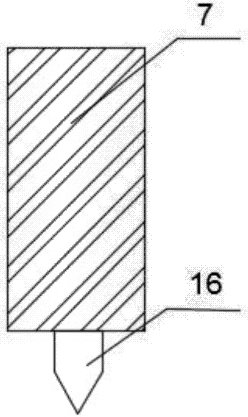
[0020] Example: such as Figure 1-3 As shown, the present invention provides a processing machine for a rotary tool post, including a main motor 1, a frame-shaped support 8, a processing shaft 11, and a support 15. The processing shaft 11 is arranged on the frame-shaped support 8, and the frame support 8 A guide screw 9 is provided on the guide screw 9, a tool holder 7 is installed on the guide screw 9, a bearing 10 is arranged in the middle of the frame support 8 and an external gear ring 6 is connected to one end of the frame support 8, and the external gear ring 6 is provided with The big gear 5, one end of the lead screw 9 is connected with a small gear B12, the small gear B12 is connected with an internal gear ring 13, and the internal gear ring 13 is equipped with a small gear A4. The left side of the big gear 5 is equipped with a toothed belt 3. The toothed belt 3 is provided with a knife holder motor 2 on the left side, and a main motor 1 is installed on the other side ...


PUM


Abstract

The invention discloses a processing machine for a rotary tool holder, which comprises a main motor, a frame-shaped support, a processing shaft and a support. A tool rest is installed, and a bearing is arranged in the middle of the frame-shaped support. One end of the frame-shaped support is connected to an external tooth ring, and a large gear is arranged on the external tooth ring. One end of the guide screw is connected to a pinion B, and the pinion B is connected to There is an inner-toothed ring, a small gear A is installed on the inner-toothed ring, a toothed belt is installed on the left side of the large gear, a knife rest motor is installed on the left side of the toothed belt, and a main motor is installed on the other side of the toothed belt. A slip ring is installed on one side of the frame motor. The specific advantage of the present invention is that the position of all the driving motors can be fixedly arranged, and the tool holder motor does not rotate with the whole machine, but acts independently. The rotating mass is thus also kept small. The high degree of automation reduces the waste of human resources.

Description

Technical field [0001] The invention relates to the field of mechanical processing, in particular to a processing machine for a rotary tool post. Background technique [0002] The machining of large machine shafts, such as turbine shafts and generator shafts, requires special lathes, which requires a large workshop. For in-situ machining, such as machining bearing fits during repairs by turning, grinding or polishing, it is desirable to use non-stationary machining that can be mounted on a fixed shaft, so as to avoid heavy and expensive disassembly and transportation work. Since transportation to the place of use and even subsequent installation work may cause damage to the shaft, reprocessing on the shaft is often required. [0003] Some lathes are known for smaller shafts, which are mounted on the shaft and rotate around the shaft. The problem in this kind of processing equipment is that the feed motion of the processing tool is generated along the shaft longitudinal and transv...

Claims


Application Information

Patent Timeline
IPC IPC(8): B23B21/00
CPCB23Q1/25
Inventor 陈芬芬
Owner 陈芬芬
Why Eureka
Try Eureka