Drives for wind power plants

A technology of wind power generation equipment and transmission device, applied in the field of transmission device and wind power generation equipment, can solve the problems of temperature rise and wear, unable to realize pure dynamic hydraulic sliding bearing, etc., and achieve the effect of reducing wear and tear

Active Publication Date: 2015-11-25
MIBA SINTER AUSTRIA
View PDF8 Cites 0 Cited by
  • Summary
  • Abstract
  • Description
  • Claims
  • Application Information

AI Technical Summary

Problems solved by technology

In particular, this results in localized temperature rises and increased wear in the region of mixed friction, so that it is hardly possible to realize purely dynamic hydraulic plain bearings in the planetary gear of a wind power plant.

Method used


Image

  • Drives for wind power plants
  • Drives for wind power plants

Examples


Embodiment Construction

[0018] First of all, it should be confirmed that in the different described embodiments the same parts are provided with the same designation or the same component designation, wherein the disclosure content contained in the entire description can be transferred to the same designation with the same designation or the same component designation. partly on. Positional indications selected in the description, such as top, bottom, side, etc., relate to the directly described and illustrated figure and, when a position is changed, are also logically transferred to the new position. Furthermore, individual features or combinations of features from the various exemplary embodiments shown and described also form an independent solution according to the invention.

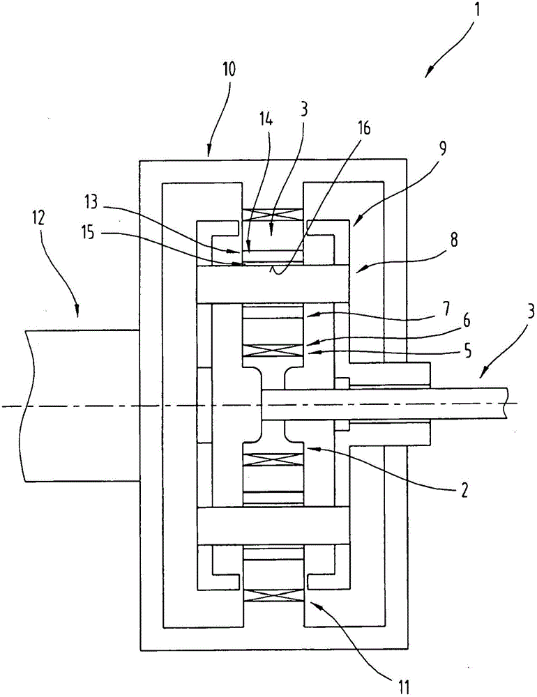
[0019] figure 1 A cutaway side view of a transmission 1 in the form of a simple planetary gear for a wind power plant is shown.

[0020] It is known that a wind power plant comprises a tower, at the upper end of which a ...


PUM

PropertyMeasurementUnit
Vickers hardnessaaaaaaaaaa

Abstract

The invention relates to a gear train (1), in particular a planetary gear train, for a wind turbine comprising a plurality of gears, in particular planet gears (4), which are each supported on a shaft (8) by means of a bearing element, wherein the bearing element is a multi-layer plain bearing (7).

Description

technical field [0001] The invention relates to a transmission for a wind power plant, in particular a planetary gear, which comprises a plurality of transmission gears, in particular planetary gears, which are each mounted on a shaft via a bearing element, The invention also relates to a wind power plant comprising a rotor and a generator, wherein a gear, in particular a planetary gear, is arranged between the rotor and the generator, which is operatively connected to the rotor and the generator. Background technique [0002] Planetary gears for wind power plants, as known for example from DE 10 260 132 A1, are used for this purpose in order to convert a relatively low rotational speed of a rotor of a wind power plant into a higher rotational speed of a generator rotor. Usually, in such planetary gears, as is also described in DE 10 260 132 A1, rolling bearings are used as bearing elements for the planet gears. [0003] Of course, EP1544504A2 already describes the use of p...

Claims


Application Information

Patent Timeline
Patent Type & Authority Patents(China)
IPC IPC(8): F16C33/02F16H57/08F03D11/02F16C33/20
CPCF16H57/041F05B2260/40311F16C33/1055F16C33/20F16C33/201F16C33/203F16C41/008F16C2202/04F16C2361/61F16H57/0479F16H2057/085F16C2202/50F16C2204/20F16C2204/36F16C2206/04F16C2208/02F16C2208/42F16C2223/60F16C2360/31Y02E10/70F16C2204/04
Inventor A·卡里C·弗斯特纳
Owner MIBA SINTER AUSTRIA
Why Eureka
Try Eureka