Electric control hydraulic drainage device

A drainage device and hydraulic technology, used in water supply devices, flushing equipment with water tanks, buildings, etc., can solve the problems of inconvenient lead-in circuits, inconvenient replacement, hidden safety hazards, etc., and achieve low manufacturing precision, low production cost, The effect of prolonging the service life

Pending Publication Date: 2017-09-08
FOSHAN SHUNDE DISTRICT KARDIER SANITARY WARE TECH CO LTD
View PDF0 Cites 2 Cited by
  • Summary
  • Abstract
  • Description
  • Claims
  • Application Information

AI Technical Summary

Problems solved by technology

[0002] The drain valve products driven by electricity on the market use a motor or an electromagnetic push rod to provide drainage. The motor or electromagnetic push rod consumes power. There are two power supply methods: 1. Household electricity AC220V is directly introduced into the power supply or powered after transformation , because the working environment is humid and it is not convenient to lead the circuit, there will be a great potential safety hazard
2. Powered by battery, due to high power consumption, it needs to be replaced frequently, and the environment is humid so that the battery box needs to be fully sealed, which is inconvenient to replace
3. The driving force of the existing electromagnetic drive device is small, so it is not suitable for use in places that require a large driving force

Method used


Image

  • Electric control hydraulic drainage device
  • Electric control hydraulic drainage device
  • Electric control hydraulic drainage device

Examples


Embodiment Construction

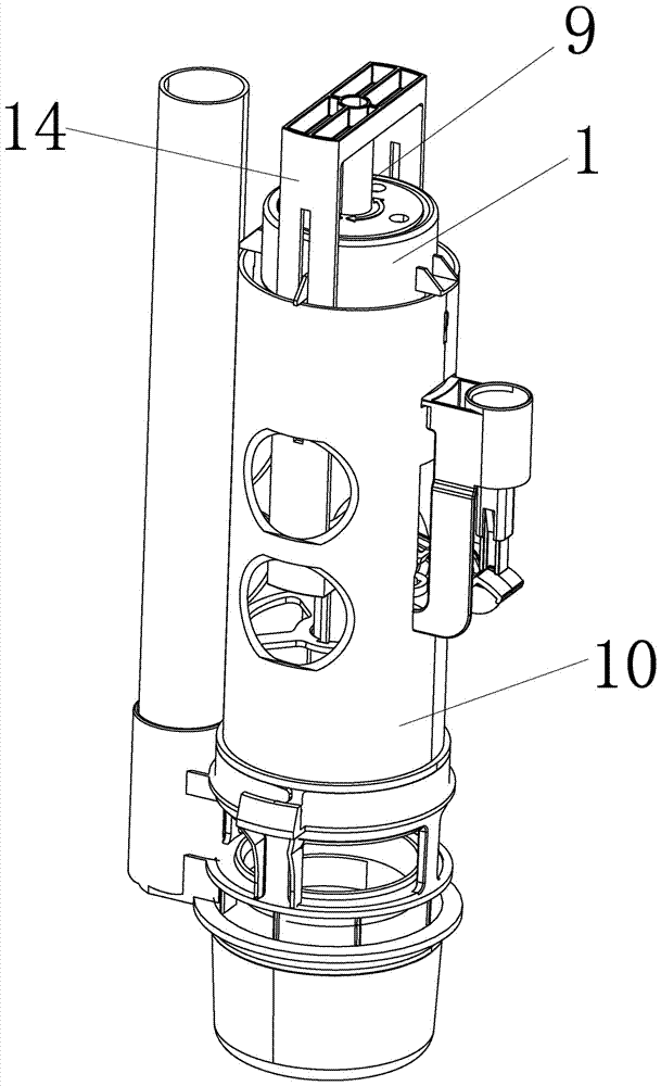
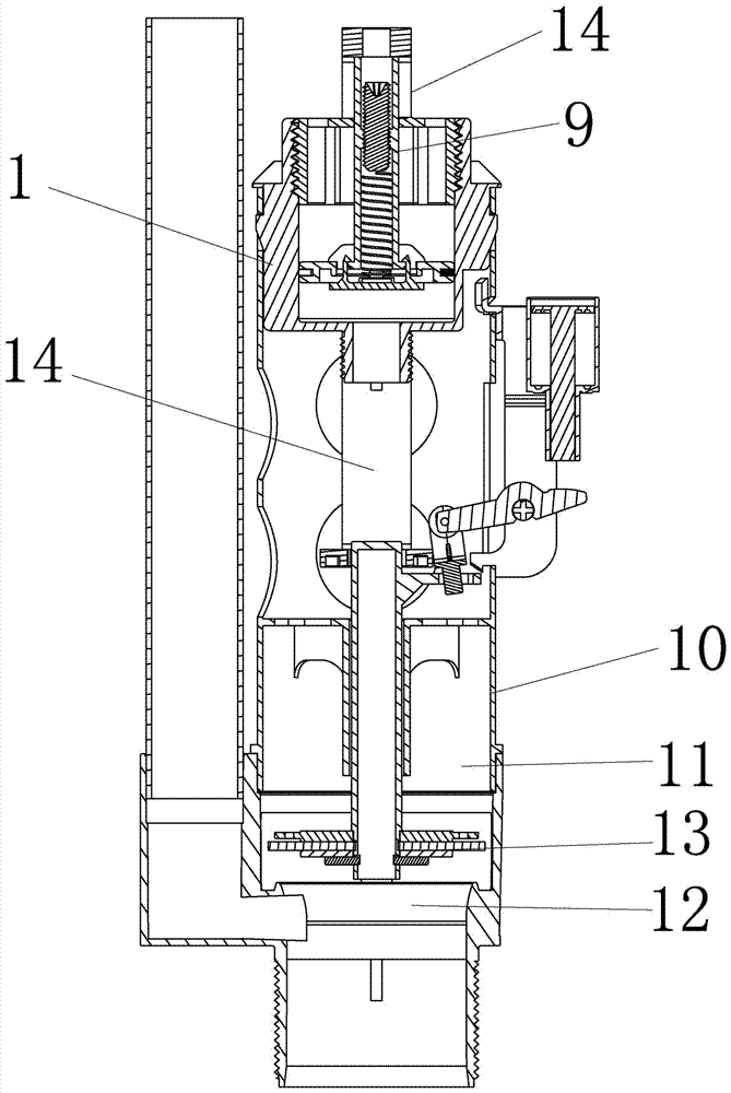
[0018] The present invention will be further described in detail below in conjunction with the accompanying drawings. An electronically controlled hydraulic drainage device is characterized in that: it comprises a casing 10 and a accommodating cavity 11 arranged inside the accommodating cavity 11, a drainage hole 12 is arranged at the bottom of the accommodating cavity 11, and a liftable drainage valve core is arranged above the drainage hole 12 13. The drain valve core 13 is covered on the drain hole 12 to stop the drainage, and the drain valve core 13 is separated from the drain hole 12 to drain water; the accommodating cavity 11 is also provided with a hydraulic drive cylinder and a drain valve core 13 is connected, and the hydraulic drive cylinder pushes the drain valve core 13 to move to realize drainage.

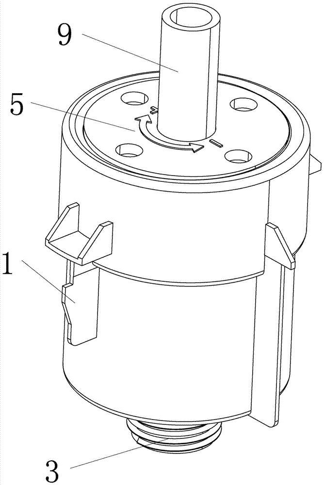
[0019] The hydraulic drive cylinder includes a cylinder body 1 and a piston 2 arranged in it. The bottom of the cylinder body 1 is provided with a water inlet 3 to con...


PUM


Abstract

An electronically controlled hydraulic drainage device, characterized in that it includes a housing and an accommodating cavity inside the accommodating cavity, a drain hole is arranged at the bottom of the accommodating cavity, a liftable drain valve core is arranged above the drain hole, and the drain valve core covers The drainage hole plays the role of cut-off drainage, and the drainage valve core is separated from the drainage hole to play the role of drainage; the accommodating cavity is also provided with a hydraulic drive cylinder connected to the drainage valve core, and the hydraulic drive cylinder pushes the drainage valve core to move, Achieve drainage. The beneficial effects of the present invention are as follows: 1. Using external tap water as the driving power can provide greater driving force for the piston, so that the driving device has greater driving force. 2. The pulse solenoid valve of the control system has low power consumption and small size, which can be easily powered by dry batteries or lithium batteries, greatly extending the service life of the batteries. 3. The hydraulic cylinder has a non-sealed structure, so its manufacturing precision is low, and there is no need to use high-precision molds and other equipment for production, which simplifies the process flow.

Description

technical field [0001] The invention relates to a drainage device, in particular to an electronically controlled hydraulic drainage device. Background technique [0002] The electric-driven drain valve products on the market use a motor or an electromagnetic push rod to provide drainage. The motor or electromagnetic push rod consumes power. There are two power supply methods: 1. Household electricity AC220V is directly introduced into the power supply or transformed into a power supply. , Because the working environment is humid and it is not convenient to lead the circuit, there will be a great safety hazard. 2. It is powered by batteries. Due to the large power consumption, it needs to be replaced frequently, and the environment is humid so that the battery box needs to be fully sealed, which is inconvenient to replace. 3. The existing electromagnetic drive device has a small driving force and is not suitable for use in places that require a large driving force. SUMMARY...

Claims


Application Information

Patent Timeline
Patent Type & Authority Applications(China)
IPC IPC(8): E03D1/34
CPCE03D1/34
Inventor 李俊德
Owner FOSHAN SHUNDE DISTRICT KARDIER SANITARY WARE TECH CO LTD
Why Eureka
Try Eureka