Receiving and transmitting integrated open light path atmospheric detection system

An open optical path, atmospheric detection technology, applied in measurement devices, material analysis through optical means, instruments, etc., can solve the problems of inability to detect, large optical path span, time-consuming and labor-intensive, etc., to shorten the distance, reduce the difficulty, and detect data. reliable results

Active Publication Date: 2017-09-08
HEFEI INSTITUTES OF PHYSICAL SCIENCE - CHINESE ACAD OF SCI
View PDF5 Cites 21 Cited by
  • Summary
  • Abstract
  • Description
  • Claims
  • Application Information

AI Technical Summary

Problems solved by technology

Most of the existing open optical path detection equipment is an open optical path of the opposite beam type, that is, the infrared signal transmitting end and the infrared signal receiving end are respectively installed in two places far away from each other, and the infrared signal passes through the atmosphere along a straight line path. The defect of this kind of testing equipment is The reason is that the infrared signal transmitting end and the infrared signal receiving end separated in two places need to adjust their installation angles precisely, and the debugging process is time-consuming and laborious. In addition, the optical path span of the through-beam optical path is relatively large, and the equipment at both ends is gathered together. Farther away, further increasing the difficulty of debugging
In addition, once the detection equipment in the prior art is adjusted in place, it can only detect the atmosphere on one path, and cannot detect other directions in the area to be measured, and the reliability of the detection data is difficult to guarantee

Method used


Image

  • Receiving and transmitting integrated open light path atmospheric detection system
  • Receiving and transmitting integrated open light path atmospheric detection system
  • Receiving and transmitting integrated open light path atmospheric detection system

Examples


Embodiment 1

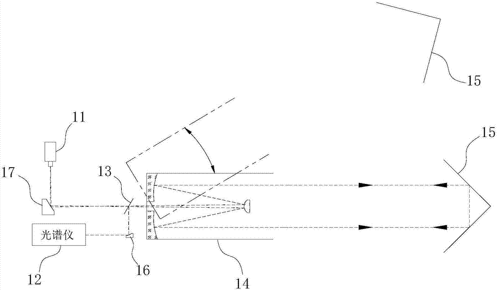
[0030] Such as figure 1 As shown, the infrared signal transmitting unit includes an infrared light source 11 and an ellipsoidal mirror 17, and the scattered light emitted by the infrared light source 11 is reflected by the ellipsoidal mirror 17 and then passes through the first beam splitter 13 and enters the Karl's telescope 14, and the Karl's telescope 14 expand the scattered light beam into collimated parallel light, the parallel light shoots to the reflection unit 15, the reflection unit 15 is composed of a corner mirror, and the parallel light returns to the Karl’s telescope 14 according to the original path after being reflected by the reflection unit 15, and passes through the Karl’s telescope 14. The telescope 14 is focused and projected on the first beam splitter 13, then reflected by the first parabolic mirror 16 into parallel light and enters the infrared signal receiving unit 12 after being reflected by the first beam splitter 13, and the infrared signal receiving u...

Embodiment 2

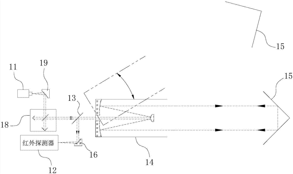
[0032] Such as figure 2As shown, the infrared signal transmitting unit comprises an infrared light source 11, a second parabolic mirror 19 and an interferometer 18, and the scattered light emitted by the infrared light source 11 is reflected into parallel light by the second parabolic mirror 19, and enters the interferometer 18 to generate an interference signal, and the interference The signal is emitted from the interferometer 18 and passes through the first beam splitter 13 and enters the Karl Fischer telescope 14. The interference signal is expanded by the Karl Fischer telescope 14 and then directed to the reflection unit 15. The reflection unit 15 is also composed of a corner mirror, and the interference signal After being reflected by the reflection unit 15, it returns to the Karl’s telescope 14 according to the original path, is projected on the first beam splitter 13 after being focused by the Karl’s telescope 14, and then reflected by the first beam splitter 13 and th...

Embodiment 3

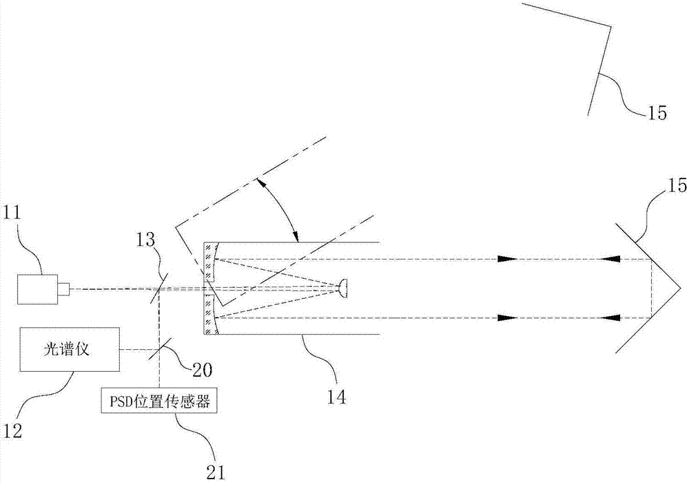
[0034] Such as image 3 As shown, the infrared signal transmitting unit includes an infrared light source 11, and the scattered light emitted by the infrared light source 11 directly passes through the first beam splitter 13 and enters the Karl Fischer telescope 14, and the beam expands through the Karl Fischer telescope 14 to be collimated parallel light. The light is projected on the reflection unit 15, and the reflection unit 15 is a corner mirror. After the parallel light is reflected by the reflection unit 15, it returns to the Karl’s telescope 14, and after being focused by the Karl’s telescope 14, it is projected on the first beam splitter 13, and then Projected on the second beam splitter 20 after being reflected by the first reflector, one of the two light beams split by the second beam splitter 20 enters the infrared signal receiving unit 12, and the other enters the PSD position sensor 21, and the infrared signal receiving unit 12 for the spectrometer. In this embo...


PUM


Abstract

The invention belongs to atmospheric infrared detection equipment, and specifically relates to a receiving and transmitting integrated open light path atmospheric detection system. The receiving and transmitting integrated open light path atmospheric detection system comprises an infrared signal transmitting unit, an infrared signal receiving unit and at least two reflection units, wherein the infrared signal transmitting unit and the infrared signal receiving unit are integrated in a machine body; an infrared light beam transmitted by the infrared signal transmitting unit is projected to the reflection units, can be returned back the way to the machine body after being reflected by the reflection units and can be incident to the infrared signal receiving unit; the at least two reflection units are distributed in a detection space zone at intervals; an emergent direction of the infrared light beam is set to be adjustable, so that the infrared light beam can be selectively projected to any one reflection unit. According to the receiving and transmitting integrated open light path atmospheric detection system disclosed by the invention, the stroke of the infrared light beam is doubled by utilizing separated reflection of the reflection units, the distance between two devices under the same stroke is shortened, and the device debugging difficulty is reduced; in the receiving and transmitting integrated open light path atmospheric detection system, the infrared light beam can be switched in several different paths, so that atmospheres in different directions in a to-be-detected zone can be detected, and detection data are more reliable.

Description

technical field [0001] The invention belongs to atmospheric infrared detection equipment, in particular to an atmospheric detection system with an integrated open optical path for sending and receiving. Background technique [0002] Air pollution is one of the major problems currently facing our country. Continuous online monitoring of ambient air, mastering the emission, diffusion and evolution of pollutant gases, and realizing accurate traceability are of great significance for formulating emission reduction policies, evaluating emission reduction programs, and thoroughly solving air pollution problems. Significance. Using the "infrared fingerprint" absorption characteristics of the gas to be measured for spectral quantitative analysis to obtain the concentration of the gas to be measured has an important application in the field of online gas detection. Gas concentration detection based on infrared spectroscopy can be divided into two methods: extractive detection and op...

Claims


Application Information

Patent Timeline
Patent Type & Authority Applications(China)
IPC IPC(8): G01N21/3504
CPCG01N21/3504G01N2021/3513
Inventor 李相贤韩昕高闽光童晶晶王亚萍陈军石建国李妍刘建国刘文清
Owner HEFEI INSTITUTES OF PHYSICAL SCIENCE - CHINESE ACAD OF SCI
Why Eureka
Try Eureka