Antenna fabrication method of terminal, antenna and terminal

A manufacturing method and antenna technology, applied in the electronic field, can solve the problems of poor weather resistance of LDS antennas, affecting the radio frequency performance of the antenna, and low strength of the paint layer, etc., and achieve the effects of strong protection, improved radio frequency performance, and high strength

Inactive Publication Date: 2017-09-08
SHENZHEN GIONEE COMM EQUIP
View PDF5 Cites 17 Cited by
  • Summary
  • Abstract
  • Description
  • Claims
  • Application Information

AI Technical Summary

Problems solved by technology
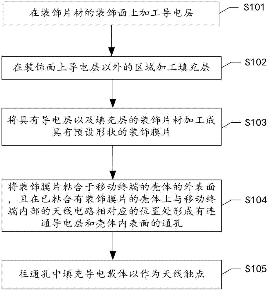
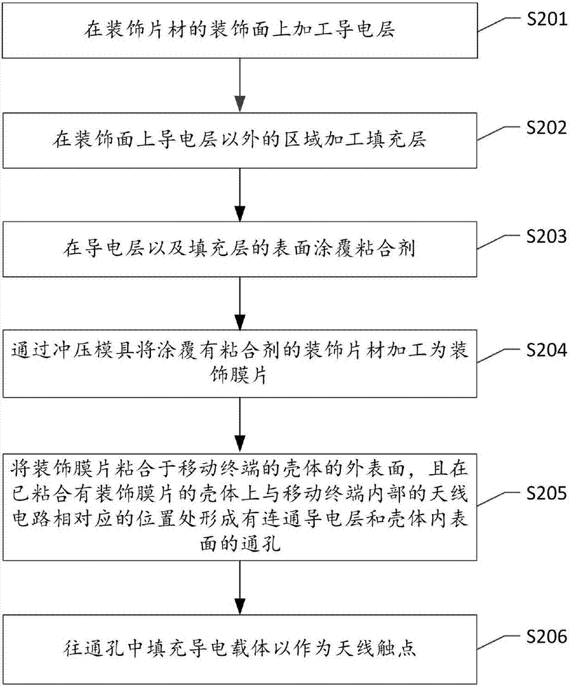
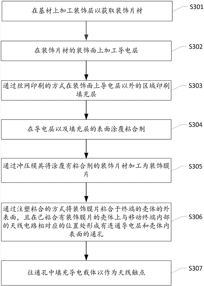
[0004] For the FPC antenna, because it needs to be installed on the inner surface of the terminal shell, the clearance of the antenna is not enough, which affects the radio frequency performance of the antenna
[0005] For the LDS antenna, since the paint layer sprayed on the outer surface of the housing is not strong, it is easily damaged by the external environment, resulting in poor weather resistance of the LDS antenna

Method used


Image

  • Antenna fabrication method of terminal, antenna and terminal
  • Antenna fabrication method of terminal, antenna and terminal
  • Antenna fabrication method of terminal, antenna and terminal

Examples


Embodiment Construction

[0028] The following will clearly and completely describe the technical solutions in the embodiments of the present invention with reference to the accompanying drawings in the embodiments of the present invention. Obviously, the described embodiments are some of the embodiments of the present invention, but not all of them. Based on the embodiments of the present invention, all other embodiments obtained by persons of ordinary skill in the art without making creative efforts belong to the protection scope of the present invention.

[0029] It should be understood that when used in this specification and the appended claims, the terms "comprising" and "comprises" indicate the presence of described features, integers, steps, operations, elements and / or components, but do not exclude one or Presence or addition of multiple other features, integers, steps, operations, elements, components and / or collections thereof.

[0030] It should also be understood that the terminology used ...


PUM


Abstract

The embodiment of the invention discloses an antenna fabrication method of a terminal. The antenna fabrication method comprises the steps of processing a conductive layer on decoration surface of a decoration sheet; processing filling layers on regions except the conductive layer on the decoration surface, wherein the thicknesses of the filling layers are same as the thickness of the conductive layer; processing the decoration sheet with the conductive layer and the filling layers to form a decoration membrane with a preset shape; pasting the decoration membrane on an outer surface of a shell of the terminal, wherein a through hole is formed in a position, corresponding to an antenna circuit in the terminal, on the shell pasted with the decoration membrane and is used for communicating the conductive layer and an inner surface of the shell; and filling the through hole with a conductive carrier to be used as an antenna contact.

Description

technical field [0001] The present invention relates to the field of electronic technology, in particular to a terminal antenna manufacturing method, antenna and terminal. Background technique [0002] With the development of thinner and lighter terminals such as mobile phones, watches, and tablet computers, the structural space reserved for antennas has become smaller. At present, an FPC (Flexible Printed Circuit, flexible circuit board) antenna or an LDS (Laser-Direct-structuring, laser direct structuring technology) antenna is mainly used in the terminal. The FPC antenna needs to be pasted on the inner side of the terminal housing or on the antenna bracket inside the terminal. The LDS antenna is made on the outer facade of the housing by electroplating and then laser engraving. [0003] However, there are following problems in the manufacturing method of the existing antenna: [0004] For the FPC antenna, since it needs to be installed on the inner surface of the termi...

Claims


Application Information

Patent Timeline
Patent Type & Authority Applications(China)
IPC IPC(8): H01Q1/38H01Q1/22
CPCH01Q1/38H01Q1/22
Inventor 李奎岳照山
Owner SHENZHEN GIONEE COMM EQUIP
Why Eureka
Try Eureka