
Wire control device and manufacturing method of shell assembly thereof

A technology of wire control device and shell assembly, which is applied in the direction of cabinet/cabinet/drawer parts, electrical components, closed cabinet, etc., can solve the problems of complex connection structure, troublesome installation and disassembly, limited modeling space, etc. , to achieve the effect of convenient installation and disassembly, convenient after-sales maintenance, and large modeling space

Pending Publication Date: 2017-09-08
中山市信轩堂文化产业投资有限公司
View PDF8 Cites 0 Cited by
  • Summary
  • Abstract
  • Description
  • Claims
  • Application Information

AI Technical Summary

Problems solved by technology

[0002] The power cord and control device are one of the necessary components for controlling the working status of heating electrical appliances. The existing control methods of heating electrical appliances are generally divided into two types: wired and wireless. The wired control method is the simplest and most commonly used control method. The wired control method mainly includes the way that the control device is integrated in the electrical appliance and the way of setting an external wire control box separately; the way that the control device is integrated in the electrical appliance is generally applied to products with larger volume; for products with smaller volume, in When the wire control circuit board or control buttons are installed on the electrical appliance, the structure of the electrical appliance will be complicated, the production cost will be high, and the smaller product will have a great impact on the wire control circuit board when it is heated, resulting in a decrease in its service life; The way of the control box, such as the wire control device of the Chinese patent CN205752819U, the wire control device concentrates the control input circuit on the power line, the wire control device uses weak current to work, and realizes control by inputting control signals to the main circuit board of the electrical appliance through the control input circuit , there is no need to set up a separate wire control line, which makes the structure of the product simpler and the product more beautiful, but the shell of the wire control device adopts a general shell cover connection structure, the connection structure is complicated, installation and disassembly are troublesome, and the modeling space is limited. Convenient after-sales maintenance

Method used


Image

  • Wire control device and manufacturing method of shell assembly thereof
  • Wire control device and manufacturing method of shell assembly thereof
  • Wire control device and manufacturing method of shell assembly thereof

Examples


Embodiment 1

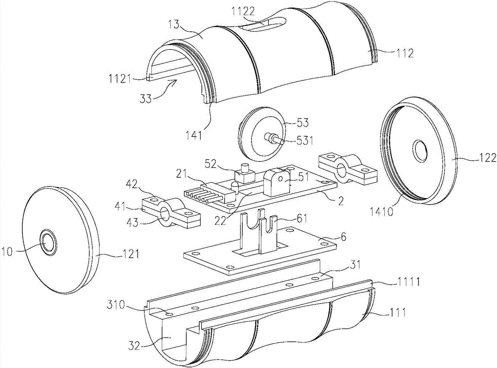
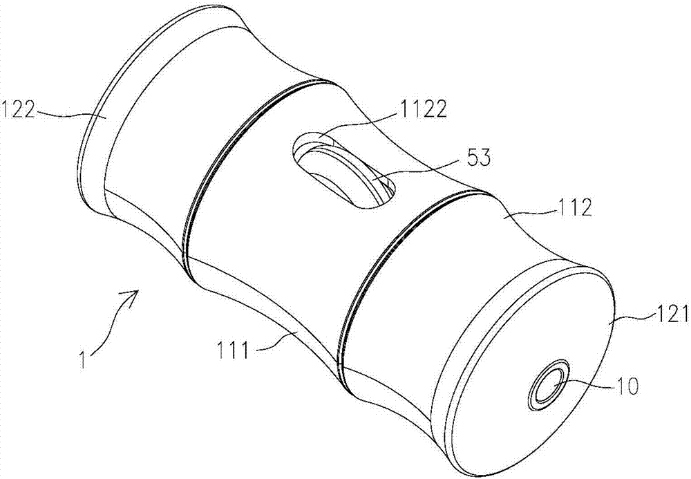
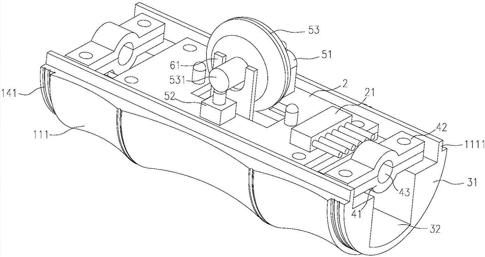
[0046] see Figures 1 to 7 , the wire control device of the present invention includes a housing assembly 1 and a wire control circuit board 2, the housing assembly 1 is provided with an electrical component cavity 3, the axial cross-sectional structure of the electrical component cavity 3 is the same, and the wire control circuit The board 2 is placed in the electrical component cavity 3, the housing assembly 1 is provided with a wire passage 10 connecting the electrical component cavity 3 and the outside world, the wire control circuit board 2 is provided with a terminal 21, and the housing assembly The assembly 1 includes a shell and an end cover. The shell includes a first shell 111 and a second shell 112 that are relatively assembled. The first shell 111 and the second shell 112 are formed by metal extrusion. The end cover includes a first end cover 121 and a second end cover 122. After the first shell 111 and the second shell 112 are assembled, the two ends thereof are f...

Embodiment 2

[0056] The difference between this implementation and the first implementation is that the first housing 111 and the second housing 112 are injection molded, and the circuit board installation recess 31, the electrical component slot 33, the splicing structure and the wire slot 32 are compatible with the first housing 111. It is integrally injection molded with the second housing 112 .

Embodiment 3

[0058] The main difference between this embodiment and Embodiment 1 is: see Figure 8 , the wire control circuit board 2 is provided with a power switch button 71 and a power adjustment button, and the position corresponding to the power switch button 71 and the power adjustment button on the second housing 112 is provided with a corresponding button hole (not shown in the figure). ), the power adjustment button includes a power increase button 72 and a power reduction button 73, the power switch button 71, the power increase button 72 and the power reduction button 73 are respectively provided with a button cap, and the button cap extends out of the second housing through the button hole The outside of 112 is controlled by the user, and the power switch button 71 is used to send a switch signal to the main control circuit of the electrical appliance, and the main control circuit of the electrical appliance controls the power on or off according to the signal of the switch; Th...


PUM


Abstract

The invention discloses a wire control device. The wire control device comprises a shell assembly and a wire control circuit board, wherein the shell assembly is internally provided with an electrical apparatus element cavity; the wire control circuit board is arranged inside the electrical apparatus element cavity; a wire passing opening for communicating the electrical apparatus element cavity and the outside is formed in the shell assembly; an amphenol connector is arranged on the wire control circuit board; the shell assembly comprises a shell and an end cover, the shell comprises a first shell and a second shell which are spliced relatively, the end cover comprises a first end cover and a second end cover, and after the first shell and the second shell are spliced, two ends of the first shell and two ends of the second shell are fixed through the first end cover and the second end cover. The invention also provides a manufacturing method of the shell assembly. Compared with the prior art, after the first shell and the second shell designed in the invention are spliced, two ends of the first shell and two ends of the second shell are connected through the first end cover and the second end cover, the shell assembly is simple in structure and convenient to mount and dismount, and after-sales repair is facilitated; and due to the fact that the connecting structures of the shell are arranged at two ends, the modeling space of the outer surface is larger.

Description

technical field [0001] The invention belongs to the technical field of wire control devices for electrical appliances, and in particular relates to a manufacturing method for wire control devices and shell components thereof. Background technique [0002] The power cord and control device are one of the necessary components for controlling the working status of heating electrical appliances. The existing control methods of heating electrical appliances are generally divided into two types: wired and wireless. The wired control method is the simplest and most commonly used control method. The wired control method mainly includes the way that the control device is integrated in the electrical appliance and the way of setting an external wire control box separately; the way that the control device is integrated in the electrical appliance is generally applied to products with larger volume; for products with smaller volume, in When the wire control circuit board or control butt...

Claims


Application Information

Patent Timeline
IPC IPC(8): H05K5/00H05K5/02H01H25/00
CPCH05K5/0004H01H25/008H05K5/03
Inventor 彭镜溪
Owner 中山市信轩堂文化产业投资有限公司
Learn More