Industrial filter drum type dust removal equipment

A kind of dust removal equipment and industrial technology, which is applied in the field of industrial filter cartridge dust removal equipment, can solve the problems of affecting the filtering effect and insufficient gas filtration of dust, so as to achieve easy blowing off, increase the storage rate, and improve work efficiency Effect

Active Publication Date: 2017-09-12
XINYI ZHONGXIN OPTOELECTRONICS TECH CO LTD
View PDF6 Cites 1 Cited by
  • Summary
  • Abstract
  • Description
  • Claims
  • Application Information

AI Technical Summary

Problems solved by technology

According to different dust removal mechanisms, dust collectors are divided into various settling chambers and cyclone dust collectors that use the gravity of the particles themselves to remove dust; various wet dust collectors that use water to remove dust; filter dust collectors that use various filter materials to remove dust Various high-voltage electrostatic precipitators that use high-voltage electrostatic field force to remove dust; and existing filter-type precipitators have some problems, such as insufficient filtration of gas containing dust, and some dust will adhere to the filter material, which will affect the filtration. Effect

Method used


Image

  • Industrial filter drum type dust removal equipment
  • Industrial filter drum type dust removal equipment

Examples


Embodiment Construction

[0018] In order to make the technical means, creative features, goals and effects achieved by the present invention easy to understand, the present invention will be further described below in conjunction with specific embodiments.

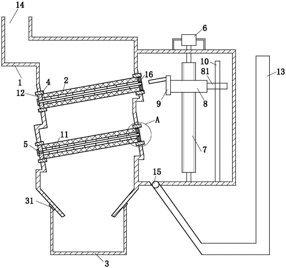
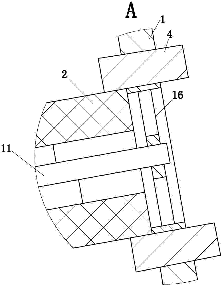
[0019] Such as Figure 1 to Figure 2 As shown, an industrial filter cartridge type dust removal equipment includes a body 1, a filter element 2, an ash bin 3, a No. 1 air bag 4, a fixed cover 5, a motor 6, a lead screw 7, a moving nut 8, an air bag 9, and a polished rod 10 , a cage frame 11, a support seat 12, an air extraction module 13 and a support ring 16, characterized in that: the upper left of the body 1 is provided with an air inlet 14, the body 1 is provided with a through hole, and the No. 1 airbag 4 is fixed on the through hole. On the hole; the support seat 12 is installed on the No. 1 air bag 4 on the left side, and the support seat 12 is provided with a through hole, and the support ring 16 is installed on the No. 1 air bag 4 on the ...


PUM


Abstract

The invention belongs to the field of industrial environmental protection, and particularly relates to industrial filter drum type dust removal equipment. The industrial filter drum type dust removal equipment comprises a machine body, filter elements, a dust bin, first air bags, fixed covers, a motor, a screw rod, a moving nut, an air pocket, a polished rod, cage frames, a supporting seat, an exhaust module and supporting rings, wherein through holes are formed in the machine body; the first air bags are fixed on the through holes; the supporting seat is mounted on the first air bags; through holes are formed in the supporting seat; the left ends of the cage frames are placed in the through holes; the fixed covers are located at the left end of the supporting seat; the filter elements are mounted on the cage frames; the screw rod is connected with the machine body through a bearing; the motor is fixed on the machine body; the moving nut is mounted on the screw rod; the lower end of the polished rod is fixed on the machine body; the air pocket is fixed at the left end of the moving nut; the exhaust module is connected with the right end of the machine body; the dust bin is located below the machine body; a second air bag is arranged between the dust bin and the machine body; the second air bag can vibrate under the action of air flow and drive the dust bin to vibrate, so that the dust can be accumulated more tightly, and the dust collection rate is increased.

Description

technical field [0001] The invention belongs to the field of industrial environmental protection, in particular to an industrial filter cartridge type dedusting equipment. Background technique [0002] In the process of stone grinding and processing, cutting machines, polishing machines, etc. will generate a lot of dust during the working process. Of course, other processing equipment such as other processing equipment will also generate considerable dust. If it is not removed in time, it will damage the equipment The health of the operating workers will have a greater impact. In order to reduce the emission of dust in industrial production and protect the atmospheric environment, people use various dust removal devices to control the pollution of particulate matter emitted by pollution sources to the atmosphere. According to different dust removal mechanisms, dust collectors are divided into various settling chambers and cyclone dust collectors that use the gravity of the ...

Claims


Application Information

Patent Timeline
Patent Type & Authority Applications(China)
IPC IPC(8): B01D46/24B01D46/00
CPCB01D46/2411B01D46/76
Inventor 刘恒蔡猛丁杰鑫
Owner XINYI ZHONGXIN OPTOELECTRONICS TECH CO LTD
Why Eureka
Try Eureka