Cathode magnetic control sputtering target device

A magnetron sputtering and target device technology, applied in sputtering coating, ion implantation coating, metal material coating process, etc., can solve the problem of small erosion area, decreased deposition rate, and decreased magnetic flux density on the surface of the target material and other problems to achieve the effect of ensuring magnetic field strength, reducing production costs and improving uniformity

Active Publication Date: 2017-09-12
48TH RES INST OF CHINA ELECTRONICS TECH GROUP CORP
View PDF6 Cites 2 Cited by
  • Summary
  • Abstract
  • Description
  • Claims
  • Application Information

AI Technical Summary

Problems solved by technology

The magnetic permeability of the magnetic material is large, and the magnetic flux density on the surface of the target is reduced, so that the closed magnetic field formed on the surface of the target is very small, and even the closed magnetic field cannot be formed on the discharge surface of the magnetic target. Correspondingly, the movement range of the electrons is small , as the sputtering progresses, the magnetic field lines are locally concentrated on the target surface, so the expansion of the plasma becomes smaller, the deposition rate decreases, and the sputtering efficiency decreases. At the same time, the erosion area is small, and only a small part of the target is sputtered. Material usage efficiency is relatively low

Method used


Image

  • Cathode magnetic control sputtering target device
  • Cathode magnetic control sputtering target device
  • Cathode magnetic control sputtering target device

Examples


Embodiment Construction

[0022] The present invention will be described in further detail below in conjunction with the accompanying drawings and specific embodiments.

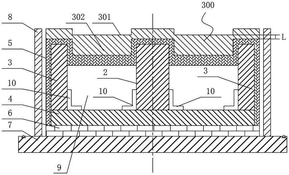
[0023] like image 3 and Figure 4 As shown, the cathode magnetron sputtering target device of this embodiment includes a magnetic target 300 and a magnet disposed on the back of the magnetic target 300. The front of the magnetic target 300 is provided with a rectangular annular groove 301, and the back of the magnetic target 300 is A rectangular annular protrusion 302 corresponding to the rectangular annular groove 301 is provided. The magnet includes a central magnet 2 and an outer magnet 3 with opposite polarities. The central magnet 2 is located at the center of the rectangular annular protrusion 302, and the outer magnet 3 is arranged There are four pieces and they are respectively arranged on the outer periphery of the rectangular annular protrusion 302 . It should be noted that the front of the magnetic target 300 is provided...


PUM


Abstract

The invention discloses a cathode magnetic control sputtering target device which comprises a magnetic target material and magnets arranged on the back face of the magnetic target material. The front of the magnetic target material is provided with a rectangular annular groove. The back face of the magnetic target material is provided with a rectangular annular protrusion corresponding to the rectangular annular groove. The magnets comprise a center magnet and outer magnets which are opposite in polarity. The center magnet is arranged in the center of the rectangular annular protrusion. The four outer magnets are arranged on the periphery of the rectangular annular protrusion. The cathode magnetic control sputtering target device has the beneficial effects of being capable of reinforcing magnetic field strength of the surface of the target material, improving uniformity of sputtering of the target material, reducing frequency of replacing the target material, reducing the production cost and the like.

Description

technical field [0001] The invention relates to magnetron sputtering coating equipment, in particular to a cathode magnetron sputtering target device. Background technique [0002] Magnetic materials are often coated by magnetron sputtering. For example, in the field of magnetic recording represented by hard disk drives, as the material of the magnetic thin film responsible for recording, it is a material based on Co, Fe or Ni, which is a ferromagnetic metal. [0003] Magnetron sputtering coating is to install a magnet on the back side of the target in a vacuum chamber so that a closed magnetic field is generated on the surface of the target along the direction perpendicular to the electric field. The closed magnetic field interacts with the electric field to make the electrons close on the target surface. The magnetic field runs in a spiral shape. During the movement, the electrons collide with the atoms of the inert gas passing into the vacuum chamber, causing them to ion...

Claims


Application Information

Patent Timeline
IPC IPC(8): C23C14/35
CPCC23C14/3407C23C14/35
Inventor 毛朝斌罗超范江华舒勇东佘鹏程胡凡彭立波
Owner 48TH RES INST OF CHINA ELECTRONICS TECH GROUP CORP
Why Eureka
Try Eureka