Liftable self-propelled continuous pushing system for large-span steel box beam and construction method thereof

A technology of jacking construction and steel box girder, which is applied in the direction of bridges, bridge construction, erection/assembly of bridges, etc., which can solve problems such as dependence on hoisting equipment, large labor demand, and long cantilever time, so as to save hoisting and dismantling costs The effects of operating procedures, reducing safety risks, and shortening construction time

Active Publication Date: 2017-09-12
CHINA RAILWAY CONSTR BRIDGE ENG BUREAU GRP OF THE FIFTH ENG +1
View PDF7 Cites 26 Cited by
  • Summary
  • Abstract
  • Description
  • Claims
  • Application Information

AI Technical Summary

Problems solved by technology

[0004] However, the existing jacking construction mainly uses the rail climber to generate reaction force through the friction force with the pier top slideway, combined with the front drag to push the beam forward, and performs cyclic operation by moving the wedge-shaped reaction seat, and dismantles the wedge-shaped reaction force in the process. The construction efficiency is low, the labor demand is large, and the hoisting equipment is overly relied on, and the traditional pure jacking construction efficiency is too low due to the safety constraints of the site terrain and the high-speed rail operation line. , the steel box girder cantilevered above the high-speed rail for too long, there are certain safety hazards

Method used


Image

  • Liftable self-propelled continuous pushing system for large-span steel box beam and construction method thereof
  • Liftable self-propelled continuous pushing system for large-span steel box beam and construction method thereof
  • Liftable self-propelled continuous pushing system for large-span steel box beam and construction method thereof

Examples


Embodiment 1

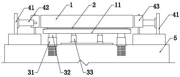
[0055] In this example, if Figure 1-Figure 8 As shown, the large-span steel box girder liftable self-propelled continuous jacking system is installed based on the pier body 5 and used for the jacking construction of the steel box girder 1, including the automatic adjustment device for the elevation of the pier top slideway, the automatic positioning continuous jacking device, The horizontal limit and deviation correction device and the pre-buried steel plate longitudinally on the top of the pier body 5 during the concrete construction of the pier body 5, the automatic adjustment device for the elevation of the pier top slideway and the lateral limit and deviation correction device are all fixedly installed on the preset steel plate;

[0056] The automatic adjustment device for the elevation of the pier top slideway is provided with two parallel pier top slideways 11, and the tops of the two pier top slideways 11 are freely placed between the top surface of the pier top slidewa...

Embodiment 2

[0066] In this example, if Figure 9 As shown, the self-propelled continuous jacking construction method of the long-span steel box girder is suitable for all long-span jacking constructions on high-speed railways, ordinary railways, highways, rivers, deep valleys and other construction obstacles. In the process, the automatic positioning continuous jacking device, the automatic adjustment device for the elevation of the pier top slideway, and the lateral limit and deviation correction device are used together to form a large-span, liftable, self-propelled continuous jacking, and no offset. Steel box girder 1 top push construction method.

[0067] The self-propelled continuous jacking construction method of the large-span steel box girder specifically includes the following steps:

[0068] Step S1: Measurement and positioning. According to the design line direction, accurately measure the position of the center line of the steel box girder 1 and whether the setting direction ...


PUM


Abstract

The invention discloses a liftable self-propelled continuous pushing system for a large-span steel box beam. The liftable self-propelled continuous pushing system for the large-span steel box beam comprises a automatically-positioning continuous pushing device, an automatic pier top slideway elevation adjusting device and a horizontal limiting and correcting device. By virtue of a highly automated control system, precise positioning and synchronous pushing are achieved, damage to the quality of a steel box structure is minimized, and a relatively good quality control effect is ensured. The invention further discloses a pushing construction method. Through arrangement of the automatically-positioning continuous pushing device and the automatic pier top slideway elevation adjusting device in a pushing construction technology, self-propelled advancement and precise positioning of the pushing device are achieved, lifting and mounting and dismounting operation procedures of mechanical equipment are saved, the operation of the construction technology is simplified, the technical difficulty is reduced, the on-site controllability is substantially improved, the construction time is shortened, the safety risks are reduced, and popularization and application are easy.

Description

technical field [0001] The present invention relates to the field of road and bridge building construction, specifically, a large-span steel box girder liftable self-propelled continuous jacking system and a construction method thereof. Background technique [0002] Since the successful application of the jacking method in the Ager Bridge in Austria in 1959, it has developed rapidly in the history of bridge construction in the world. China also used the jacking method to build the Dijiahe Bridge for the first time in 1977. In 2004, the Millau Bridge in France used multiple The completion of the point-flexible orthogonal jacking method marks that the world’s jacking technology has reached a new level. According to statistics, there are more than 1,000 bridges built using the jacking method in the world, of which China accounts for more than a hundred. [0003] The construction of the jacking method is very different from the support method, hoisting method, swivel method, and...

Claims


Application Information

Patent Timeline
Patent Type & Authority Applications(China)
IPC IPC(8): E01D21/00
CPCE01D21/00Y02E10/20
Inventor 苏春生张庆何十美梁朋刚汤振亚
Owner CHINA RAILWAY CONSTR BRIDGE ENG BUREAU GRP OF THE FIFTH ENG
Why Eureka
Try Eureka