Automatic gear grease lubrication pump

A grease lubrication and gear pump technology, applied in the direction of lubrication pump, engine lubrication, lubricating oil container, etc., can solve problems such as difficulty in implementation, and achieve the effect of compact structure, convenient and flexible location setting, and convenient maintenance and use.

Pending Publication Date: 2017-09-12
许永久
View PDF8 Cites 1 Cited by
  • Summary
  • Abstract
  • Description
  • Claims
  • Application Information

AI Technical Summary

Problems solved by technology

There is also the pressure relief valve arranged in the pump, how to unload the pressure grease in the tens of meters long main oil supply pipeline to the "0" state is also difficult to achieve

Method used


Image

  • Automatic gear grease lubrication pump
  • Automatic gear grease lubrication pump
  • Automatic gear grease lubrication pump

Examples


Embodiment Construction

[0037] The present invention will be described in further detail below in conjunction with the accompanying drawings of the embodiments.

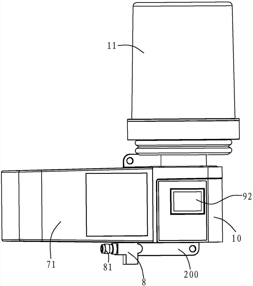
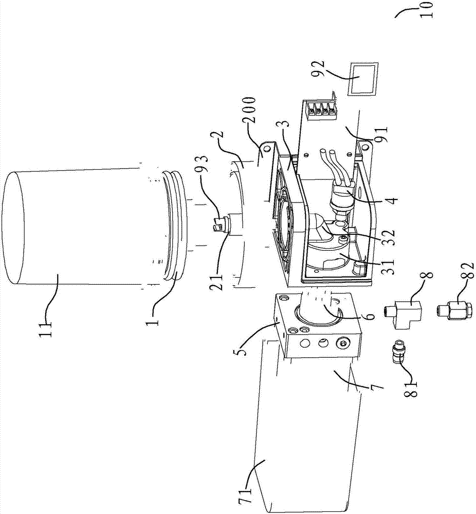
[0038] Such as Figure 1 to Figure 3 As shown, the automatic gear grease lubrication pump in this embodiment includes a telescopic grease tank 1, a fixed seat 2, a pump seat 3, a pressure switch 4, a flow channel block 5, a gear pump 6, a motor 7, and an air release valve 81 , Lack of oil detector 93, alarm, control device.

[0039] Wherein the grease tank 1 is used for containing lubricating grease, is particularly suitable for containing 0#~2# software grease, and this grease tank 1 outer jacket is provided with cover 11. The grease tank 1 in this embodiment is upside down, and the outlet of the telescopic grease tank 1 is located at the bottom of the grease tank 1 . When subjected to external force, the grease in the grease tank 1 will be automatically sent out by pressure from the outlet.

[0040] The fixed seat 2 is fixed on the upp...


PUM


Abstract

The invention relates to an automatic gear grease lubrication pump which comprises a grease tank, a fixed seat, a pump seat, a flow channel block, a gear pump, a motor, a control device and the like. The grease tank can extend and retract. The fixed seat and the flow channel block are mounted on the pump seat. The grease tank and a cover cap are mounted on the fixed seat. The motor and an oil pump group are mounted on two sides of the flow channel block. A grease flow channel, a pressure relief flow channel, an overflow flow channel and an oil outlet flow channel are formed in the flow channel block. The pressure relief flow channel and the overflow flow channel communicate with the grease flow channel. The oil outlet flow channel communicates with the pressure relief flow channel. A pressure relief valve is arranged in the pressure relief flow channel. An overflow valve is arranged in the overflow flow channel. The control device is connected with the motor to control the motor to work. The automatic gear grease lubrication pump can realize full-automatic control, can quick relief pressure after oil supply, and ensure that a pressure relief type quantitative distributor can normally work.

Description

technical field [0001] The invention relates to an automatic gear grease lubricating pump. Background technique [0002] Intelligent automatic quantitative oil lubrication is the best choice for lubrication in all mechanical equipment. At present, there are basically two types of automatic quantitative centralized lubrication devices (that is, intelligent refueling equipment) at home and abroad to meet the different requirements of lubricating oils with different viscosities: [0003] 1. The gear pump is equipped with a thin oil automatic quantitative centralized lubricating device with a pressure relief quantitative distributor structure, which is suitable for fluid or semi-fluid lubricants. In order to meet the requirements of the working principle of the pressure relief quantitative distributor, this type of device must unload the main oil supply pipeline from the oil pump to the distributor to the "0" state after completing one oil supply, so as to ensure that the press...

Claims


Application Information

Patent Timeline
Patent Type & Authority Applications(China)
IPC IPC(8): F16N13/20F16N23/00F16N29/04F16N21/00F16N19/00
CPCF16N13/20F16N19/00F16N21/00F16N23/00F16N29/04F16N2260/08F16N2270/70
Inventor 许永久
Owner 许永久
Why Eureka
Try Eureka