Gas producer furnace and gas generating device

A technology of gas generator and furnace body, which is applied in the field of heat treatment, which can solve the problems of slowing down the production rhythm, increasing the construction cost, and increasing the difficulty of operation, and meets the requirements of reducing the height of the factory building, reducing the possibility of shaking, and reducing the difficulty of operation Effect

Pending Publication Date: 2017-09-12
江苏丰东热技术有限公司
View PDF6 Cites 0 Cited by
  • Summary
  • Abstract
  • Description
  • Claims
  • Application Information

AI Technical Summary

Problems solved by technology

In this way, there is a requirement for the height of the factory building. The height of the factory building must be enough for the muffle tank to be hoisted for maintenance, which increases the difficulty of the factory building and also greatly increases the construction cost.
[0003] On the other hand, in the process of hoisting the muffle tank, the stability requirements for the muffle tank are high, the operation requirements are high, and the operation difficulty is correspondingly increased.
If a collision occurs during the lifting process, it is easy to cause additional damage to the muffle tank, increase the maintenance cost, and prolong the maintenance cycle of the muffle tank, which is not conducive to the progress of production and slows down the production rhythm
[0004] In addition, in some places where the space height is limited, the maintenance of the muffle tank will become very difficult and inconvenient, and the popularization and use of the existing gas generator will also be greatly restricted

Method used


Image

  • Gas producer furnace and gas generating device
  • Gas producer furnace and gas generating device
  • Gas producer furnace and gas generating device

Examples


Embodiment

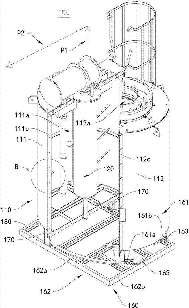
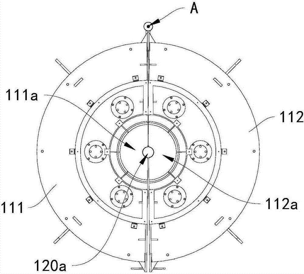
[0043] see figure 1 and figure 2 , this embodiment provides a gas generator 100 . The furnace body 110 of the gas generator 100 includes a first furnace body 111 and a second furnace body 112 . The first furnace body 111 has a first sub-cavity 111a, and the second furnace body 112 has a second sub-cavity 112a. Set cavity 120a. Wherein, the first furnace body 111 and the second furnace body 112 are detachably connected, and the first furnace body 111 and the second furnace body 112 can be separated from each other through disassembly.

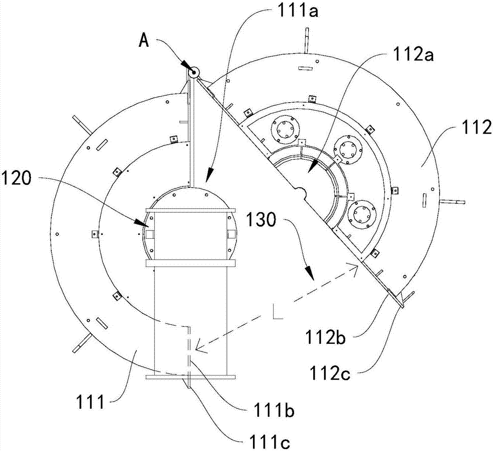
[0044] The furnace body 110 of the gas generating furnace 100 is composed of a first furnace body 111 and a second furnace body 112 that can be separated from each other. By separating the first furnace body 111 and the second furnace body 112 from each other, the muffle tank 120 can be separated from The sides of the main body 110 are removed from the accommodating cavity 120 a without being lifted from the top of the furnace main body 110...


PUM


Abstract

The invention discloses a gas producer furnace and a gas generating device, and relates to the technical field of heat treatment. The gas producer furnace comprises a furnace body. The furnace body comprises a first furnace main body and a second furnace main body. The first furnace main body is provided with a first sub cavity, and the second furnace main body is provided with a second sub cavity. The first sub cavity and the second sub cavity are used for forming a containing cavity used for containing a Muffle tank. The first furnace main body and the second furnace main body are detachably connected so that the first furnace main body can be separated from the second furnace main body. The gas generating device comprises the gas producer furnace. Both the gas generating device and the gas producer furnace can be used in a workshop with the small height, the Muffle tank can be maintained conveniently, stability and safety of the Muffle tank in the maintaining process are improved, and collision is avoided. The application range of the gas producer furnace and the gas generating device is widened.

Description

technical field [0001] The invention relates to the technical field of heat treatment, in particular to a gas generator and a gas generator. Background technique [0002] In the existing gas generator, when the muffle tank in the furnace is being maintained, the muffle tank needs to be hoisted out from the top of the furnace body so that the muffle tank is higher than the furnace top cover, so as to facilitate maintenance and repair of the muffle tank. In this way, there is a requirement for the height of the factory building. The height of the factory building must be sufficient for the muffle tank to be hoisted for maintenance, which increases the difficulty of building the factory building and greatly increases the construction cost. [0003] On the other hand, in the process of hoisting the muffle tank, the stability requirements for the muffle tank are relatively high, the operation requirements are high, and the operation difficulty is correspondingly increased. If a ...

Claims


Application Information

Patent Timeline
Patent Type & Authority Applications(China)
IPC IPC(8): F27B5/02F27B5/06F27B5/10
CPCF27B5/02F27B5/06F27B5/10
Inventor 卞健姜辛
Owner 江苏丰东热技术有限公司
Why Eureka
Try Eureka