Optical triggering measuring head and measurement method
A probe and optical technology, applied in the field of optical trigger probe and measurement, can solve the problems of low trigger accuracy and large anisotropy, and achieve the effect of simple and quick installation, strong applicability and high measurement resolution
- Summary
- Abstract
- Description
- Claims
- Application Information
AI Technical Summary
Problems solved by technology
Method used
Image
Examples
Embodiment
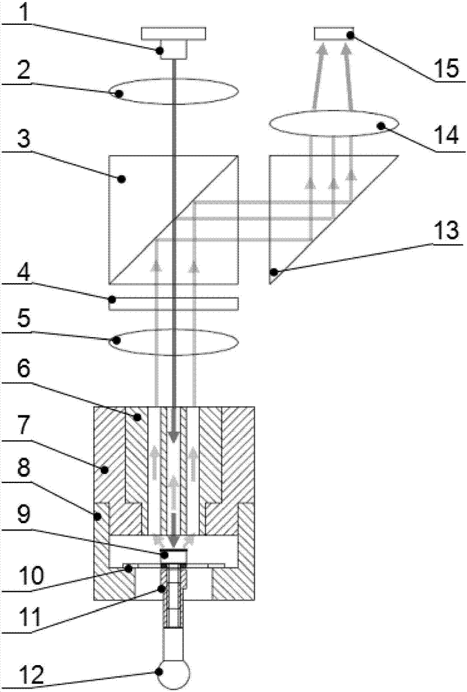
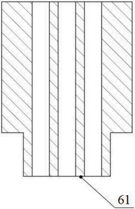
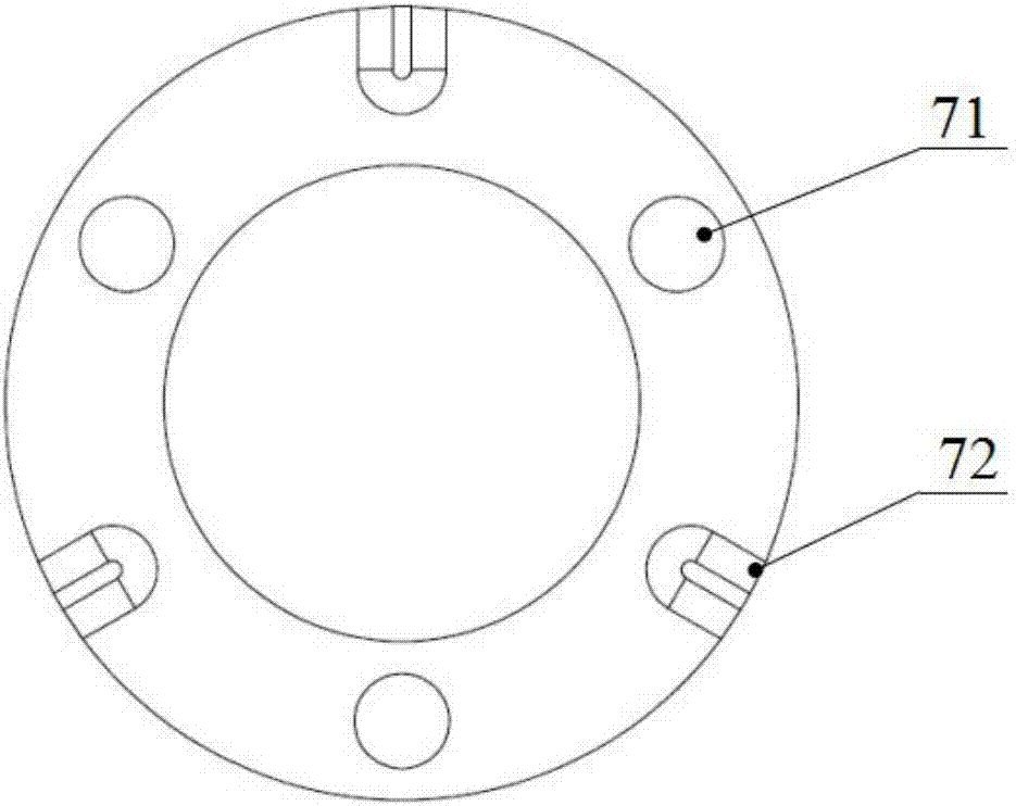
[0028] Such as Figure 1 to Figure 4 As shown, an optical trigger probe shown in this embodiment includes two parts: the probe optical path module and the probe sensing module. The probe optical path module includes focusing lenses 15 and 1 / 4 Wave plate 4, polarizing beam splitting prism 3, collimating lens 2, laser diode 1 and the rectangular prism 13 that is arranged on polarizing beam splitting prism 3 sides, the focusing lens 2 14 that is located at rectangular prism 13 rears and photodetector 15 successively; Wherein The laser diode selects visible light with a wavelength of 650nm, and the optical components of the optical path module of the probe match the components of the 650nm band. Square space, the fast axis direction of quarter wave plate 4 and the included angle of P-type polarized light vibration direction are 45 °, the right-angled surface of right-angled prism 13 is opposite to polarization splitter prism 3, another right-angled surface of right-angled prism 13...
PUM
 Abstract
Description
Claims
Application Information
 - R&D
- Intellectual Property
- Life Sciences
- Materials
- Tech Scout
- Unparalleled Data Quality
- Higher Quality Content
- 60% Fewer Hallucinations
Browse by: Latest US Patents, China's latest patents, Technical Efficacy Thesaurus, Application Domain, Technology Topic, Popular Technical Reports.
© 2025 PatSnap. All rights reserved.Legal|Privacy policy|Modern Slavery Act Transparency Statement|Sitemap|About US| Contact US: help@patsnap.com


