Quick rotary ultra-width pendular satellite imaging method

An imaging method and ultra-large-scale technology, which is applied in the field of satellite ultra-large-width swing-sweep imaging, can solve problems such as inability to solve seamless splicing imaging, and inability to meet ultra-large-width imaging in ground areas

Active Publication Date: 2017-09-12
HARBIN INST OF TECH
View PDF7 Cites 13 Cited by
  • Summary
  • Abstract
  • Description
  • Claims
  • Application Information

AI Technical Summary

Problems solved by technology

[0006] The purpose of the present invention is to solve the method that can only be used for static push-broom imaging, large-angle dynamic push-broom imaging, or satellite static mirror swing imaging for satellites. In order to solve the problem of seamless stitching imaging between orbital imaging areas, a fast-rotating satellite ultra-large-width swing-sweep imaging method is proposed

Method used


Image

  • Quick rotary ultra-width pendular satellite imaging method
  • Quick rotary ultra-width pendular satellite imaging method
  • Quick rotary ultra-width pendular satellite imaging method

Examples


specific Embodiment approach 1

[0031] Specific implementation mode 1: A satellite fast-rotating ultra-large-width push-broom imaging method according to this implementation mode is specifically prepared according to the following steps:

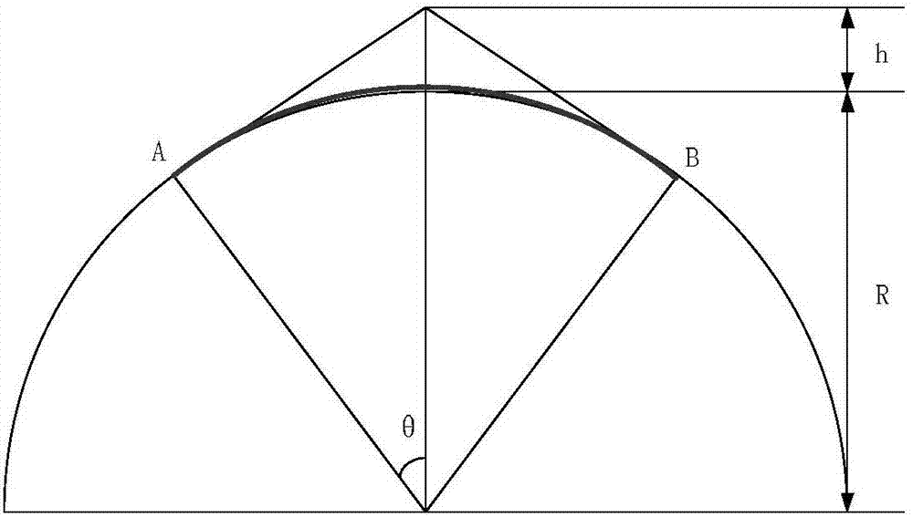
[0032] Step 1. Assuming the satellite orbit height h, take the earth radius R, and calculate the curve distance between the two points AB on the curve of the satellite orbit corresponding to the central angle 2θ That is, the width L perpendicular to the track 5 ,Such as image 3 shown;

[0033] Step 2. Assuming that the detector's field of view is η, calculate the detector's field of view L according to the field of view and the orbital height 1 That is, the width of the flight direction as Figure 4 shown;

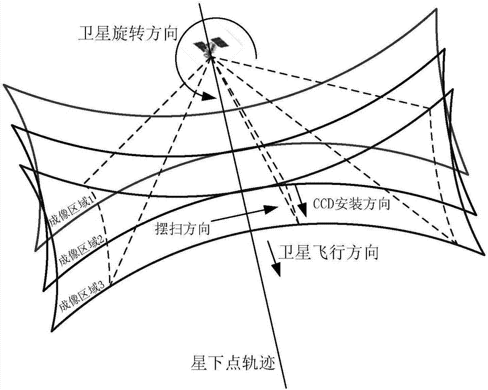
[0034] Step 3. Only when there is no gap between the two adjacent imaging areas of the detector can the ultra-large width be achieved. See the schematic diagram of the imaging area figure 2 , that is, the distance L between the center of the optical axis of the ...

specific Embodiment approach 2

[0051] Specific embodiment 2: The difference between this embodiment and specific embodiment 1 is: the width L perpendicular to the track described in step 1 5 Calculated as follows:

[0052] Central angle

[0053] Width perpendicular to track Other steps and parameters are the same as those in Embodiment 1.

specific Embodiment approach 3

[0054] Specific embodiment three: the difference between this embodiment and specific embodiment one or two is: the width L of the flight direction described in step two 1 Specifically:

[0055] Other steps and parameters are the same as those in Embodiment 1 or Embodiment 2.


PUM


Abstract

The invention discloses a quick rotary ultra-width pendular satellite imaging method, and relates to ultra-width pendular imaging methods. By the aid of the quick rotary ultra-width pendular satellite imaging method, the problems of incapability of meeting ultra-width imaging requirements on ground regions by conventional imaging methods and incapability of carrying out seamless splicing imaging on imaging regions of two adjacent orbits of a single satellite can be solved. The quick rotary ultra-width pendular satellite imaging method includes steps of firstly, computing the widths L<5> perpendicular to orbits; secondly, computing the widths L<1> in flight directions; thirdly, determining whether critical values of distances L2 of the centers of the optical axes of detectors on tracks of sub-satellite points on earth surfaces are the widths L<1> of the flight directions or not; fourthly, computing the spinning speeds of the detectors along the directions of the orbits; fifthly, computing corresponding resolution ratios A<c> of the detectors during ultra-width imaging under various orbit conditions; sixthly, computing horizontal frequencies F of CCD (charge coupled devices); seventhly, computing superposition distances L<6> among imaging regions of every two corresponding orbits and the like. The quick rotary ultra-width pendular satellite imaging method has the advantage that the quick rotary ultra-width pendular satellite imaging method can be applied to the field of ultra-width pendular imaging.

Description

technical field [0001] The invention relates to a satellite ultra-large-width swing-scan imaging method, in particular to a satellite fast-rotating ultra-wide-width swing-sweep imaging method. Background technique [0002] Push-broom imaging of satellites is generally done by placing the detector perpendicular to the flight direction of the satellite, and collecting images one line at a time as the satellite flies forward. The size of the image range depends on the field of view of the CCD in the detector. Generally, a larger field of view can be achieved by splicing multiple CCDs or increasing the side swing capability of the camera at the same time. This is currently the most common imaging method for optical remote sensing satellites. The satellite's swing imaging uses a mirror to reflect light into the detector, and uses the back and forth swing of the mirror to collect a measurement value on a pixel. This imaging method has expensive and easily damaged moving parts an...

Claims


Application Information

Patent Timeline
Patent Type & Authority Applications(China)
IPC IPC(8): G01C11/02
CPCG01C11/025G01C11/02B64G1/1021B64G1/242B64G1/244H04N23/695
Inventor 曹喜滨金光王峰徐伟
Owner HARBIN INST OF TECH
Why Eureka
Try Eureka